
Follow the roving from the can to the bobbin
A roving frame must do more than make a lighter strand. It must give that strand enough cohesion for handling, wind it without unwanted stretch and build a package that feeds well at the ring frame. A neat-looking bobbin proves only part of that task.
Roving frame settings work together. Delivery speed affects twist at a given flyer speed. Package diameter changes the speed difference needed for winding. Rail motion controls where the coils lie. A fault can appear when these motions no longer match, even though each displayed number looks plausible.
This guide explains the relationships through one set of original teaching calculations. The values are illustrative, not approved recipes for a fibre blend or machine. Use the applicable machine instructions and a material trial when choosing actual settings.
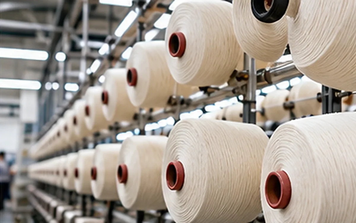
In a conventional short-staple route, drawn sliver leaves its can and passes through guides to the drafting system. The rollers reduce its linear density. The emerging strand then reaches the flyer top, follows the flyer’s guide path and passes through the presser arrangement onto the bobbin. The flyer and bobbin rotate, while the rail moves the package along its length.
Toyota’s FL200 description gives one modern example of this path. It describes an internal tubular guide connected to the presser. A separate Toyota flyer patent describes the flyer legs and a presser paddle acting on the package surface. These sources describe particular designs; guide details vary between machines.
Name the four motions before changing them
The word “speed” is incomplete unless it names the moving part and its unit. Use the following distinctions in a setting sheet or trial report.
Quantity | Usual unit | Main role in the calculation |
|---|---|---|
Front-roller delivery | m/min | Length of strand delivered per minute |
Flyer rotation | revolutions/min | Nominal twist insertion |
Bobbin rotation | revolutions/min | Winding through motion relative to the flyer |
Bobbin-rail travel | mm/min | Axial placement of successive coils |
A roller’s rotational speed is also different from its surface speed. To find surface speed, multiply revolutions per minute by circumference. Keep the roller diameter in metres if the required answer is metres per minute.
The draft uses feed and delivery surface speeds. The winding calculation uses relative rotation and the current package diameter. Interchanging these speeds can give a numerical answer with no physical meaning.
Record whether a machine value is a setpoint or a measured value. A command entered on the screen does not prove that every position delivers the expected motion. Equally, a machine with electronic drives may express the recipe differently from a frame with change wheels. The physical relationships still apply, but the way the machine achieves them differs.
Set the count through a clear draft balance
Assume a single 4.8-ktex sliver feeds each position. The required roving is 600 tex, which equals 0.6 ktex. Both counts use the same moisture and test basis.
Ideal material draft = feed linear density ÷ output linear density.
Draft = 4.8 ÷ 0.6 = 8.
If the front rollers deliver 24 m/min, the ideal feed speed is:
Feed speed = 24 ÷ 8 = 3 m/min.
The mass-flow check is straightforward because 1 ktex equals 1 g/m:
Input: 4.8 g/m × 3 m/min = 14.4 g/min.
Output: 0.6 g/m × 24 m/min = 14.4 g/min.
This balance assumes steady operation without waste loss or unintended extension outside the defined drafting zone. Actual measurements may differ from nominal roller ratios. Check the measurement basis and the material path before treating that difference as a drafting-setting error.
If the mill uses roving hank, convert it before dividing. An inverse count system becomes finer as its number rises; tex becomes coarser as its number rises. ApparelDiary’s guide to yarn count systems provides the conversion basis. Never divide a feed value in ktex by an output value in Ne.
Divide the draft without changing the total by accident
For an ideal system with two drafting zones, total draft is the product of the two zone drafts. Suppose the break draft is 1.20 and the required total is eight:
Main draft = 8 ÷ 1.20 = 6.667.
If break draft becomes 1.30 while total draft must remain eight:
Main draft = 8 ÷ 1.30 = 6.154.
These calculations explain the ratio change. They do not select a suitable break draft. A real arrangement may include other defined ratios, so confirm the machine’s terms before using the calculation.
Changing break draft while leaving every other speed ratio unchanged can alter total draft and output count. A trial may then compare two counts as well as two drafting conditions. Preserve the intended total, or state clearly that the trial also changes roving count.
Calculate twist from flyer speed and delivery
In the basic flyer model, each flyer revolution inserts one turn into the delivered strand. The Indian government’s NIMI textile-mechatronics training text explains this twist-insertion principle. Nominal twist is therefore:
Twist, turns/m = flyer revolutions/min ÷ delivery, m/min.
With a flyer speed of 864 rpm and delivery of 24 m/min:
Nominal twist = 864 ÷ 24 = 36 turns/m.
The units cancel correctly: revolutions per minute divided by metres per minute gives turns per metre. In inch units, 36 turns/m equals 36 × 0.0254 = 0.9144 turns/inch.
This is the nominal process relationship. A laboratory result also depends on how the specimen is taken and tested. Do not use the winding speed difference in place of flyer speed in this twist formula.
At a fixed flyer speed, raising twist reduces delivery. If the target changes from 36 to 45 turns/m:
New delivery = 864 ÷ 45 = 19.2 m/min.
Delivery falls by 20%, even though twist rises by 25%. The percentages have different starting values. To retain 24 m/min at 45 turns/m, the nominal flyer requirement would be 1,080 rpm.
Neither calculation approves the higher speed. The frame, flyer, fibre and package must all suit the operating condition. The Rieter F37 brochure distinguishes mechanical limits from speeds and drafts that depend on material and roving count. A catalogue maximum is not a target for every lot.
Keep the twist ratio when changing delivery
A planned speed change needs a matching flyer speed if nominal twist is to stay constant. For the 36-turns/m example, a settled delivery of 12 m/min requires:
Flyer speed = 36 × 12 = 432 rpm.
Suppose instead that delivery is held at 12 m/min while the flyer is held at 691.2 rpm, which is 80% of the original 864 rpm. The nominal twist at those settled speeds would be:
691.2 ÷ 12 = 57.6 turns/m.
Both motions have slowed, yet the twist ratio has risen by 60%. Saying that the machine ran at a “lower speed” would hide that change. The report needs both speeds and the period to which they apply.
This example compares steady operating points. It does not predict the exact twist in every centimetre during acceleration or braking. A real transition also involves the material already in the path and the response of the drives. Use the machine’s coordinated start and stop sequence, not separate manual changes based on this simplified ratio.
If a fault appears after each restart, retain samples from the affected length and from normal running. Record which stage of the restart produced them. Do not combine those samples before checking whether their properties differ. A good result from settled production does not explain a recurring start-up fault.
Judge twist at the next process as well
The roving needs enough cohesion to survive winding, transport and withdrawal. It must also draft at the ring frame. A change that reduces breaks on the roving frame may create a different problem later.
Test candidate twist levels with the same feed and roving count. Keep the ring-frame trial conditions comparable. Record breaks during package withdrawal, visible stretch before the drafting zone and any undrafted sections in the yarn. Where a fault appears matters as much as the total count of breaks.
Do not assume that the same turns per metre give the same behaviour at another roving count. The strand has changed, so repeat the assessment. If a recipe uses a twist multiplier, retain its count system and unit convention when transferring it.
ASTM D1423/D1423M covers direct-counting twist measurement and states that its spun-yarn procedure also applies to rovings. Its public guidance warns that specimen rotation and package withdrawal can alter the result. The complete method has conditions and limits that the laboratory must follow.
For example, do not pull a specimen from a bobbin in an arbitrary way and then compare it with a carefully prepared sample. Mark the package location and follow the same withdrawal procedure. Retain both the nominal machine value and the measured twist, including its direction.
Winding depends on the speed difference
For the bobbin-leading example used here, the bobbin rotates faster than the flyer. The relative motion winds the roving onto the package. As the package grows, each relative revolution takes up more length.
Ignoring the small extra length from the coil’s helix, the relationship is:
Winding speed = π × package diameter × (bobbin rpm − flyer rpm).
Use diameter in metres to obtain winding speed in m/min. Match the ideal winding speed to delivery when the model assumes no stretch or slack.
Required speed difference = delivery ÷ (π × package diameter).
Keep the earlier delivery of 24 m/min and flyer speed of 864 rpm. The required values become:
Current package diameter | Required speed difference | Calculated bobbin speed |
|---|---|---|
40 mm | 190.99 rpm | 1,054.99 rpm |
80 mm | 95.49 rpm | 959.49 rpm |
120 mm | 63.66 rpm | 927.66 rpm |
The bobbin remains faster than the flyer, but the difference falls as the package grows. Holding the initial difference of 190.99 rpm at 120 mm would demand about 72 m/min of take-up in this model. That is three times the 24 m/min delivery.
The point is the mismatch, not a prediction of exactly how a real roving will fail. The strand, package and drive may respond before that state is reached. Use the maker’s tension-control and build procedure; do not test a large mismatch by forcing the machine to run.
NPTEL’s builder-mechanism lesson explains bobbin lead, flyer lead and changing package diameter. Its conventional drive example uses cone drums and a differential. Modern drive systems may achieve the required motion electronically. A bobbin-lead calculation should not be copied unchanged to a flyer-lead arrangement.
Coordinate the rail with the winding coils
The rail distributes roving along the bobbin. Winding at one height would create a narrow pile of material, regardless of whether the speed difference was correct.
For a simple uniform-pitch model:
Rail speed = coil pitch × relative revolutions per minute.
Here, pitch is the axial distance between neighbouring coils. Assume a pitch of 2.0 mm per relative revolution. At the three package diameters above, the calculated rail speeds are:
Package diameter | Relative speed | Rail speed at 2.0-mm pitch |
|---|---|---|
40 mm | 190.99 rpm | 381.97 mm/min |
80 mm | 95.49 rpm | 190.99 mm/min |
120 mm | 63.66 rpm | 127.32 mm/min |
This example ignores reversal time and uses the same circular winding approximation as before. In a real build, the pitch, compressed strand size and package shape must suit the material. Two millimetres is a chosen teaching value, not a recommended setting.
At 80 mm, an ideal 300-mm traverse would take 300 ÷ 190.99 = 1.571 minutes. A shorter later traverse would take less time at that same rail speed. Keep traverse length separate from traverse speed when reading a build setting.
The package ends also need a controlled shape. The NPTEL lesson describes reversing the rail and shortening successive layers to form tapered ends. A change in lift or end taper changes the package geometry. It should not be used as an unexplained cure for a tension fault.
Treat package growth as a measured condition
The winding equation uses the diameter where the strand is being laid. It does not use the bare-tube diameter throughout the doff. Nor does a full-bobbin diameter describe the early layers.
Package diameter depends on how much material is wound and how it packs. A harder package can occupy a different volume from a softer package of the same mass. This is why the build model needs more than a final weight target.
Toyota describes a package-formation learning function on the FL200. It predicts and corrects diameter growth using operating data. This is a feature of that control system, not evidence that every machine can use the same growth value.
A change of fibre, roving count or winding condition should prompt a review of the package data used by the actual machine. If a stored recipe is reused, check what its diameter-growth and tension fields mean. A familiar recipe name does not establish that every underlying assumption is still valid.
Measure package shape at defined locations. If the top, middle and bottom differ, one diameter reading cannot describe the whole package. Keep the method consistent so that a genuine build change is not confused with a different measuring point.
Investigate tension without turning it into a guess
Tension is part of the process, but it is not interchangeable with twist or package hardness. Several interacting conditions affect the result. A tighter package alone does not prove that the roving will feed better.
Isshi, Nakazawa and Matsuhashi’s experimental study of roving winding examined flyer resistance, relative motion, package properties and roving mass. It found linked changes during package build. The apparatus was an older simplex frame, so its numerical settings are not current recipes. Its useful lesson is to examine these responses together.
Start with the location of the concern. A break between the front rollers and flyer suggests a different inspection area from a loose layer at the bobbin end. A problem confined to early layers calls for evidence from that stage, not just a sample taken after the doff.
Check the approved guide path and the condition of its contact surfaces. Also verify tube seating, the relevant drive and the build stage when the fault occurs. Changing several tension-related parts or settings at once makes the outcome harder to explain.
Sensor coverage needs care too. The F37 brochure describes optical tension measurement at the first three positions, alongside individual roving-break monitoring. These are different forms of coverage. A statement that tension is monitored does not mean that every position has its own tension reading.
Where the concern is local, inspect and sample that position under the approved procedure. Avoid reaching into moving equipment or making an improvised adjustment to a running flyer.
Check the whole doff, not just its outside
Divide the study by package build: early, middle and late. Preserve position identity and the order in which the samples were produced. The layer visible on the outside of a full package represents the latest winding, not the start.
The following fictional count results illustrate why the average is not enough. Each build region contains one-third of the tested length, and every value uses the same conditioning and length method.
Build region | Measured linear density | Difference from 600 tex |
|---|---|---|
Early | 630 tex | +5.0% |
Middle | 600 tex | 0.0% |
Late | 570 tex | −5.0% |
The equal-length average is 600 tex. A check of that average alone would hide the change through the package. A single result from the outside would suggest 570 tex and miss the earlier heavy section.
Use these figures to plan an investigation, not to assign a cause. The pattern might involve the feed, drafting, winding or sampling. Compare the material before winding where the approved method allows it, and retain the trace of package growth. Do not assume that every build-related count change is a tension fault.
For evenness testing, ASTM D1425/D1425M includes roving in its public scope. It identifies conditions that must match for meaningful comparisons. Use the same measurement definition, test length, speed, atmosphere and sample preparation. A cut-length mass check and a capacitance CV answer related but different questions.
Reconcile package mass, length and production
Separate tube mass from material mass. If a full bobbin weighs 1.48 kg and its empty tube weighs 0.28 kg:
Net roving mass = 1.48 − 0.28 = 1.20 kg.
At a mean count of 600 tex, or 0.6 g/m, the corresponding length is:
Length = 1,200 g ÷ 0.6 g/m = 2,000 m.
At a constant 24 m/min, the ideal running time to wind that length is 83.33 minutes. This ignores breaks, speed changes and doffing. If the machine reports a different length, check the count, tare and length basis before changing the recipe to match the weight.
The same inputs give a per-position running output of:
24 m/min × 0.6 g/m × 60 min/h ÷ 1,000 = 0.864 kg/h.
For an illustrative 100-position frame, continuous output would be 86.4 kg/h. If running time is 90% of scheduled time, and that allowance already includes all stops and doffs, scheduled output is 77.76 kg/h. Apply no second doffing deduction to that same allowance.
An alternative cycle calculation can show the doffing effect explicitly. If each position winds 1.20 kg in 83.33 running minutes and a doff adds four minutes, average output is:
100 × 1.20 × 60 ÷ (2,000 ÷ 24 + 4) = about 82.44 kg/h.
This second case includes only the stated doffing loss. It should not be compared with the 90% case as though both include the same losses. The assumed four-minute doff is not a maker’s performance claim.
Release a recipe on the evidence it needs
A useful recipe identifies the feed, roving count, twist direction and level, drive settings and build programme. It also identifies the machine and the conditions under which the trial succeeded. Keep the actual test results with it.
Release should depend on a complete package that can be handled and unwound as intended. Check its count through the doff, twist, evenness and shape, then assess the resulting yarn under the planned ring-frame conditions. A successful empty-bobbin start does not establish late-build performance.
When a trial fails, change the part of the system supported by the evidence. A count error needs a count and flow check. A build fault needs attention to relative winding motion and rail travel. A weak or resistant roving needs a material and twist assessment that includes the next process.
The aim is a stable path from incoming sliver to usable yarn. That requires the four motions to agree with one another, and the measured material to agree with the assumptions used in the calculations.
References
Rieter F37 roving-frame brochure. Drive, build, monitoring and material-dependent operating limits.
Toyota FL200: productivity and package-formation control. Flyer guide path and diameter-growth control on the described machine.
Toyota Industries patent JP7545793B2: roving-frame flyer. Published design description, including flyer and presser arrangement.
NPTEL, Yarn Manufacture II: Builder Mechanism, Part I. Winding methods and conventional package-building principles.
NIMI and Directorate General of Training: Textile Mechatronics, Semester 3, Trade Theory. Roving twist and bobbin building, printed page 32.
Isshi, Nakazawa and Matsuhashi: Experiment on Winding of Roving, Part 2. Historical experiments on interacting winding conditions.
ASTM D1423/D1423M-16(2022): twist by direct counting. Public scope and specimen-handling guidance.
ASTM D1425/D1425M-14(2020): evenness by capacitance testing. Public scope and comparison conditions for textile strands, including roving.



Discussion0
Loading the discussion…