
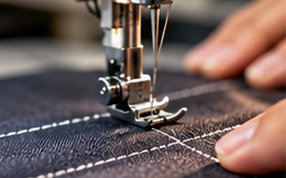
Two packets can both say Nm 90 and contain needles that should not replace one another. The number describes a size. It does not prove that the shank fits the clamp, the eye sits at the right height or the point suits the material.
Reading a needle starts with its shape and ends with its complete identity. The butt, shank, shoulder, blade, grooves, scarf, eye and point all have different jobs. Knowing those jobs helps you read a maker's drawing, describe a concern and check a replacement against the approved part.
This guide uses original examples to connect needle anatomy with everyday replacement decisions. It does not provide universal timing settings or a rule that one needle will sew every fabric. Use the manual for the exact machine and the approved specification for the operation.
Keep system, size and point separate
A needle system identifies the design needed by a machine. Size and point shape are further choices within a suitable system. Groz-Beckert makes this distinction in its needle-selection guidance: the machine must accept the system, while size and point also depend on the sewing task and material.
Write these fields separately in a sample record. “Fine ballpoint needle” describes a general idea. It leaves the system and exact size open. “Nm 90” is more precise about size but says nothing about the point. Neither is a complete replacement instruction.
The machine model is part of the check. Include its suffix and any relevant conversion or attachment. Two heads with similar names may have different documented options. An operator's memory of another machine is useful background, but it does not establish compatibility for the head in front of them.
Where a supplier lists alternate system names, use its documented cross-reference. A similar code or a shared size number is not enough. Keep the reference with the approved part record so that a later buyer does not have to repeat the guess.
Map the needle from the clamped end to the tip
The following table gives a working vocabulary. It groups parts by their place and task, rather than treating every visible feature as a separate adjustment.
Part or region | Where to find it | Main purpose |
|---|---|---|
Butt | Upper end that enters the holder | Provides the end used when seating the needle |
Shank | Thick section held by the clamp | Locates and supports the needle |
Shoulder | Transition from shank to blade | Connects the thicker and slimmer regions |
Blade or shaft | Main working length below the shank | Carries the lower features through the material |
Long groove | Channel along the blade toward the eye | Gives the needle thread a protected route |
Short groove, where provided | Near the eye on the loop-forming side | Helps the thread form its loop |
Scarf | Recess near and above the eye | Provides room for the hook or looper |
Eye | Opening near the lower end | Carries the thread through the material |
Point and tip | Penetrating end below the eye | Enter the material with the chosen point shape |
The SCHMETZ needle guide describes the main regions and their variations. Coats provides further detail on the grooves and scarf in All About Needles. Designs differ, so compare the actual system with its own drawing. Do not assume that every groove or reinforced region has the same form on every needle.
Butt, shank and shoulder are different features
The butt is at the upper, inserted end. The shank is the section held by the clamp. The shoulder is the transition below that section. These names remain the same if a loose needle is turned upside down on a desk.
A clear description should therefore use part names rather than “the bottom bit.” In a packet photograph, the needle may point upward. On the machine, its point normally faces the work. A location described only by the photograph's top or bottom can become misleading.
Shank shape also needs attention. Home-machine needles often have a flat on the shank; industrial designs can use other shapes. Sailrite's anatomy guide describes round, grooved and threaded forms among industrial examples. A flat-side rule learned on a home machine should not become a rule for every industrial head.
The shoulder's basic role is a transition in shape. Do not assume it enters every fabric stack or always makes a larger hole during sewing. Whether a given region reaches the material depends on the needle, machine motion and stack being sewn. Its name alone does not establish that contact.
Follow the working blade to the eye
The blade carries the features that interact with the cloth and thread. Some designs have a reinforced or tapered region, so a single diameter does not describe the entire profile. Groz-Beckert's apparel needle guide distinguishes the blade, reinforced area, scarf and length to the start of the eye.
That matters when someone measures a loose needle. A reading across the shank cannot be used as the blade size. A reading at a reinforced section may also be the wrong basis for the stated metric size. Identify the measuring location before comparing numbers.
The eye is the opening for the thread. Its shape and size can vary between designs, even when the needles share a nominal size. Record the complete product designation when an enlarged or specially shaped eye is part of the approved choice. “Same thickness” does not establish the same thread passage.
Distinguish grooves from the scarf
The long groove runs toward the eye and gives the thread a route along the needle. The scarf is a recessed area that gives the hook or looper clearance. They are not two names for the same feature.
When checking a drawing, first identify the view being shown. A face view may reveal the long groove clearly while hiding much of the scarf. A side view can make the recess easier to see. Turning the drawing changes the view; it does not change the required orientation on the machine.
Suppose a service note says “scratch near the groove.” That description leaves several questions. Is the mark inside the long groove, on the eye edge or on the scarf? Is it on the side facing the thread supply or the loop-forming part? A marked location on the correct maker's drawing is more useful than guessing from the word “near.”
Read metric size without turning it into a universal rule
In the metric system, Nm gives the nominal blade diameter in hundredths of a millimetre. Coats places the measurement above the scarf, away from a reinforced part. For this relationship:
Nominal diameter in mm = Nm number ÷ 100.
Metric size | Nominal diameter |
|---|---|
Nm 70 | 0.70 mm |
Nm 80 | 0.80 mm |
Nm 90 | 0.90 mm |
Nm 100 | 1.00 mm |
Nm 110 | 1.10 mm |
Consider a proposed change from Nm 80 to Nm 90. The nominal diameter rises by 0.90 − 0.80 = 0.10 mm, or 100 micrometres. Relative to the original diameter, the increase is 0.10 ÷ 0.80 × 100 = 12.5%.
Changing from Nm 90 to Nm 100 adds the same 0.10 mm. This time the relative increase is 0.10 ÷ 0.90 × 100 ≈ 11.1%. The percentage differs because the starting diameter differs.
These calculations describe nominal geometry. They do not predict a matching percentage change in penetration force, fabric damage or seam strength. They also do not specify shank diameter, overall length or the size of the eye opening.
Keep the sizing convention visible. A packet may show both metric and another size number. SCHMETZ, for example, uses paired labels such as 75/11 in its guide. The second number is not a decimal diameter or a percentage. Read it using the maker's chart, rather than dividing every number on the packet by 100.
The needle size is also separate from a sewing-thread ticket number. A thread marked 80 and a needle marked Nm 80 do not form a verified pair merely because the numbers match. Record both products fully; assess their suitability for the operation through the agreed sewing trial.
Compare dimensions from the same reference points
A dimension is useful only when its endpoints are clear. A drawing may measure from the butt to the start of the eye. Another may give total length to the tip. Those are different dimensions even if both are called “needle length” in an informal message.
For a purely illustrative comparison, suppose two technical drawings give these values:
Drawing | Butt to start of eye | Butt to tip |
|---|---|---|
Candidate A | 32.0 mm | 35.0 mm |
Candidate B | 33.5 mm | 36.0 mm |
The butt-to-eye difference is 33.5 − 32.0 = 1.5 mm. The overall-length difference is 36.0 − 35.0 = 1.0 mm. They are not interchangeable comparisons.
Measured from the start of the eye to the tip, A has 35.0 − 32.0 = 3.0 mm. B has 36.0 − 33.5 = 2.5 mm. The two drawings differ in more than one part of their geometry.
These are invented drawing values, not specifications for real needle systems. They show why holding two tips level or comparing total length alone cannot establish the same eye position. No compatibility tolerance is implied by the example.
Now consider a dimension sent without units. A note saying “eye length 32” could refer to the wrong feature as well as the wrong unit. Ask for the labelled drawing or exact part code. Do not resolve missing dimensions by installing an uncertain part and seeing whether the machine will turn.
A ruler comparison can expose an obvious mismatch. It cannot prove that two systems are equivalent. The shank, eye position, scarf, blade form and other specified features must agree with the approved machine requirement.
Check the scale before measuring a picture
An enlarged illustration can make small features easier to name, but its printed width is not the needle's diameter. Suppose a drawing explicitly uses a 10:1 scale. A nominal 0.90 mm blade would appear 9.0 mm wide at that scale. A 1.00 mm blade would appear 10.0 mm wide. Their 1.0 mm difference on the drawing represents only 0.10 mm on the parts.
Those values assume the drawing remains at its stated scale. Printing it with a fit-to-page option or changing an image's size breaks that assumption. A photograph without a reliable scale gives even less basis for a dimension check. Perspective may also make one region appear wider than another.
Use labelled dimensions from the approved technical information when identifying a part. A teaching illustration helps locate the scarf or eye; it does not replace the maker's dimensioned specification. Keep the full drawing title and revision with a saved extract so that an enlarged detail is not mistaken for an independent product specification later.
Point shape describes how the end meets the material
The point is the penetrating region and the tip is its extreme end. Neither promises damage-free sewing. The appropriate shape depends on the material and operation, and its condition matters as well.
SCHMETZ's round-point guide separates several forms, including a normal round point and light or medium ball points. Its light ball point is intended to move textile yarns aside. “Ballpoint” therefore needs a more exact description when it appears in a production record.
The same maker's cutting-point guide covers edges designed to cut materials such as leather. It also explains that the cutting orientation can affect stitch appearance. A cutting point is not simply a stronger version of a textile point.
For a mixed assembly, consider every layer that the needle enters. A point selected for a leather panel may also pass through a woven lining or tape. An acceptable result in the outer layer does not settle what happened inside the join. The approved choice needs to work with the complete assembly.
Do not translate point codes between brands from memory. A supplier's chart should identify the exact form represented by its code. Preserve that code when a sample is approved, along with the size and system. A substitute described only as “similar point” leaves a meaningful change unresolved.
Surface treatment and special geometry add further choices
Needle colour is not a complete material specification. A coating can be a deliberate product feature, and colour bands may serve a separate identification purpose. Read the packet and maker's coding guide before deciding what a visible colour means.
SCHMETZ describes hard-chrome and specialised surfaces in its industrial needle coating guidance. Its NIT and SERV 100 products address particular sewing conditions. These are product options, not evidence that any coated needle fits a given machine or lasts for a fixed number of hours.
Special geometry can change more than the outside appearance. Groz-Beckert describes designs with altered eye, scarf and blade regions for particular applications. Those details explain why a suffix should remain in the replacement record. Removing it can erase part of the approved specification.
Suppose an approved needle has a special eye geometry and a coating. A stock item matches the base system, point and Nm size but lacks the suffix. Treat the difference as an unresolved specification change. The item may be a candidate for review; it is not automatically the same approved part.
Avoid judging service life from the coating name alone. Record actual sewing conditions and the agreed replacement rule. A claim about improved wear resistance does not supply a universal change interval for every cloth, speed and operation.
Work through a three-packet replacement case
Imagine an operation whose approved record gives a complete needle system, Nm 90, a specified light ball point and a named surface treatment. The labels below are invented comparison records. They do not represent catalogued products.
Candidate | System | Size | Point and surface | Initial decision |
|---|---|---|---|---|
A | Matches the approved system | Nm 90 | Both match | Check complete code and condition |
B | Matches the approved system | Nm 100 | Both match | Size change needs review |
C | Different system | Nm 90 | Both appear similar | Compatibility is unproved |
Candidate A is the best match on these listed fields. It still needs the complete part code and correct condition. If the package identity is doubtful or a suffix is missing, the comparison is incomplete.
Candidate B increases nominal diameter from 0.90 to 1.00 mm. That is the 11.1% size change calculated above. It may fit the system, but it changes the approved sewing setup. Do not present it as a like-for-like replacement merely because it came from the same range.
Candidate C matches the size number yet fails the system check. A shared Nm value does not resolve its shank, eye position or other geometry. Keep it out of the replacement decision until an authoritative compatibility reference answers those questions.
This case gives the person issuing needles a clear question to ask: “Which complete approved designation am I replacing?” It avoids a request based only on the nearest packet, the apparent thickness or the operation's general name.
Keep the comparison attached to the operation
The same garment may use several machine types. A needle approved for a joining seam is not automatically approved for embroidery, button sewing or a special attachment. Record the operation and head identity beside the part designation.
ApparelDiary's apparel PLM guide explains how approved product details can stay linked to their revision. Use that link to keep the needle choice with the correct seam, thread and material specification. A packet kept beside an old sample cannot show whether a later revision changed the requirement.
Get orientation from the exact machine instructions
Correct orientation places the needle features where the machine expects them. It is not established by the label facing the operator or by a universal rule that every flat side must face backward.
Use the stated insertion depth, orientation and fastening method for the exact head. JUKI's DDL-8700 manual, for example, has separate needle-attachment and needle-to-hook sections. Its technical instructions distinguish needle arrangements rather than treating every system as interchangeable. It requires power off and the motor at rest before the relevant work.
A replacement task should restore an approved setup. It should not become an unrecorded timing change made to accommodate an uncertain needle. If the documented part does not seat or align as expected, stop the substitution and resolve the part or machine question.
Keep clearance checks and adjustments with trained personnel and the applicable manual. A visible scarf gives the hook or looper room; it does not specify how much clearance to set. Copying a numerical gap from another model can defeat the purpose of checking the system first.
When a drawing uses “front,” “left” or “right,” establish the maker's viewing direction. A photograph taken from behind the head reverses an observer's view. Use identifiable machine features and the labelled manual view to remove that ambiguity.
Inspect condition without losing the part's identity
A correct part can still be unsuitable because it is damaged or worn. SCHMETZ lists damaged needles among possible causes of thread shredding, skipped or uneven stitches and fabric problems. Those symptoms are reasons to investigate; they do not prove a needle fault in every case.
With the machine safely stopped, follow the approved routine for removal and inspection. Use suitable light and magnification to describe the point, eye and blade condition. Avoid testing a tip with a finger or trying to improve its shape with a file. A changed surface is no longer the supplied geometry.
Keep the replacement packet available until its identity has been recorded. If loose needles from different packets have been mixed, appearance alone may not restore their full identity. Resolve the uncertainty through the workplace's controlled issue process.
An inspection note should name the feature and observation. “Visible burr at the eye edge” is more useful than “bad needle.” It lets a technician relate the mark to the thread path without assuming that every later thread break has the same cause.
Confirm the result on the intended assembly
After the approved replacement and machine checks, sew the agreed sample using the actual material stack and thread. Review both faces and the difficult parts of the operation. A flat scrap may not represent a folded edge, junction or reinforced area in the garment.
Record whether the replacement restored the expected result. If a larger size, different point or altered surface was tested, identify that as a change trial. Keep it separate from a routine replacement with the same approved part.
Appearance is one part of the review. Required seam strength, movement and care checks remain attached to the product specification. A needle that makes an attractive row is not, on that evidence alone, approved for every use of the garment.
ApparelDiary's guide to quality assurance and quality control in garment factories helps place the replacement check within the wider quality process. Record the actual part, the relevant setup and what the sample showed. That makes the decision useful when another person repeats the operation.
Reading a needle well is a practical skill. Identify its regions, interpret its codes on the right basis and check the complete designation against the machine and operation. That sequence turns a small replacement part into a clear, repeatable instruction.



Discussion0
Loading the discussion…