
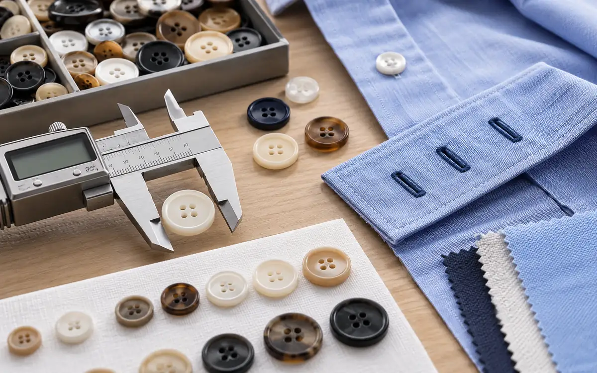
A button marked 24L is about 15.24 mm across under the standard button-ligne conversion. That number does not tell you whether it will pass through a buttonhole, sit flat on a cuff or survive garment care.
Button size is therefore a small specification with a wide effect. A mistaken conversion can lead to the wrong purchase. The conversion can be correct yet the closure may work poorly. Thickness, shape and attachment also matter.
Use ligne to identify the size family. Use dimensions and a sewn trial to define the working button.
What does button ligne mean?
In button sizing, one ligne is one fortieth of an inch. With 25.4 mm in an inch:
1L = 25.4 ÷ 40 = 0.635 mm.
The conversion works in both directions:
Diameter in millimetres = ligne × 0.635.
Equivalent ligne = diameter in millimetres ÷ 0.635.
Polkom’s size guide gives this conversion and describes measuring the widest button diameter. Plassan Button also states the 0.635 mm relationship.
Apply this unit specifically to button sizing. Do not assume that every historical use of the word “ligne” refers to the same measure.
The letter L is a size unit, not a material grade or quality level. A 24L shell button and a 24L plastic button can share a nominal face size. Their thickness, mass, edge shape and performance may still differ greatly.
An accurate ligne conversion table
The following values are calculated from 0.635 mm per ligne. The exact-conversion column avoids the mixed rounding often found in trade charts.
Button size | Calculated millimetres | Calculated inches |
|---|---|---|
12L | 7.620 | 0.300 |
14L | 8.890 | 0.350 |
16L | 10.160 | 0.400 |
18L | 11.430 | 0.450 |
20L | 12.700 | 0.500 |
22L | 13.970 | 0.550 |
24L | 15.240 | 0.600 |
26L | 16.510 | 0.650 |
28L | 17.780 | 0.700 |
30L | 19.050 | 0.750 |
32L | 20.320 | 0.800 |
36L | 22.860 | 0.900 |
40L | 25.400 | 1.000 |
48L | 30.480 | 1.200 |
60L | 38.100 | 1.500 |
These calculated values are not manufacturing tolerances. A chart may show three decimal places. That does not set a tolerance of one thousandth of a millimetre for the supplier.
A catalogue may round a 24L size to 15.2 mm. A drawing may use 15.0 mm as a particular product’s nominal diameter. Clarify which statement controls the supplied part. Do not silently treat all three descriptions as identical.
Worked conversions and the rounding trap
Suppose an unknown button measures 15.00 mm across.
Equivalent ligne = 15.00 ÷ 0.635 = 23.62L, approximately.
That result suggests a nearby trade size such as 24L. It does not prove that the sample was manufactured to a 24L drawing.
Does the buyer need an exact replacement? Send the measured dimensions, shape and sample identity. Ordering “24L” alone could deliver a button closer to 15.24 mm. Its profile could also differ.
For a second example, a 30L button converts to:
30 × 0.635 = 19.05 mm.
A chart that rounds this to 19.0 mm is useful for quick recognition. That rounding is only a display choice. It does not change the specified buttonhole or measurement limit.
Keep full precision through a calculation. Then round the result to suit the measurement method. A ruler may read to the nearest millimetre. It cannot then show that a button is precisely 19.03 mm.
Separate nominal size, actual size and tolerance
These three terms answer different questions.
Nominal size identifies the intended product or size family. Actual size is a measurement of a particular specimen. Tolerance defines the permitted departure from the specified dimension.
For a hypothetical button, the buyer and supplier agree on a diameter of 15.20 mm with a tolerance of ±0.15 mm.
The permitted interval is therefore:
15.05 mm to 15.35 mm.
A measured diameter of 15.32 mm falls within that interval. A diameter of 15.40 mm does not. Calling both samples 24L would not remove the difference.
This example is a teaching specification, not an industry-wide tolerance. Real limits should reflect the button process, measurement capability and closure function.
Also decide how roundness will be checked. A round button might measure 15.10 mm in one direction and 15.33 mm at right angles. Both readings may fit the diameter interval. The variation can still matter for appearance or fit. State any separate roundness requirement. Nominal size alone does not define it.
Measure the button without changing it
Choose a tool that can resolve the difference that matters. A calliper often suits routine diameter and thickness checks. Complex outlines or small features may need an optical method. A profile projector is one possible tool.
Before measuring, check the tool’s condition and zero. The decision may call for a reference check. In that case, use a suitable reference to confirm the tool’s response. Clean the contact faces and remove loose material from the button.
For a round button, place the jaws across the widest part of the face. Keep the button square to the jaws. Rotate it and repeat so that one accidental chord is not mistaken for the full diameter.
Use light, consistent contact. Excess force can compress a covered button or deform a soft part. Keep the calliper aligned on a curved face. Tilting it may give a reading that differs from the intended face diameter.
Record the tool, dimension definition and number of pieces checked. If two operators disagree, first compare how they hold the part. More decimal places will not solve an unclear measurement method.
Read a small set of measurements correctly
The mean diameter can look correct. Yet one button may lie outside the agreed limits. Keep the individual readings when size controls a functional fit.
Consider five hypothetical measurements: 15.10, 15.14, 15.18, 15.20 and 15.38 mm. Their total is 76.00 mm, so their mean is 15.20 mm. That matches the nominal diameter in the earlier example.
However, 15.38 mm exceeds that example’s upper limit of 15.35 mm. The mean does not make the fifth button conform. It differs from the smallest measured button by 0.28 mm. This spread shows why a single sample is weak evidence of consistency.
This example explains how to read the data. It does not set a shipment sampling plan. Follow the agreed inspection plan when choosing specimens and their number. The importance of the dimension should guide that plan.
For a reading close to a limit, consider whether the method can resolve the decision. A soft covered button may give different readings with different contact forces. An irregular edge may make the contact location unclear. Repeating the same unclear method many times does not remove those problems.
Agree how borderline results will be handled before inspecting a disputed lot. Use a better-defined method or an appropriate measurement review when needed. Avoid adding an informal tolerance simply because the result is inconvenient.
Finally, keep specimens identifiable. Suppose the largest button is used in the tightest-opening trial. Keep its identity linked to its measured dimensions. Otherwise the team may think it tested a difficult combination. In fact, it may have used average parts.
Define irregular shapes with a drawing
A single ligne size is especially weak for oval, square, toggle or shaped buttons. The longest dimension alone cannot describe how the part passes through an opening.
For an oval button, state major length, minor width and thickness. For a square button, state side length and corner form. Add the maximum diagonal if it matters to the passage path.
A hypothetical oval button measures 20 mm long and 12 mm wide. Calling it roughly 31.5L from its longest dimension hides the 12 mm width. Two buttons with that same long dimension could need quite different buttonholes.
Use a simple dimensioned outline with a marked face and attachment side. State which feature defines the supplier’s trade size. Avoid asking the factory to infer orientation from a photograph.
When replacing a shaped button, compare its movement through the opening. A rounded edge may slide through where a sharp shoulder catches. The maximum length could be the same in both cases.
Thickness changes the closure
A flat button and a domed button of equal diameter do not pass through an opening in the same way. Their three-dimensional profiles matter.
New Mexico State University’s buttonhole guide explains which button features affect buttonhole size. Shape and thickness matter alongside diameter. It recommends testing the actual button before making the garment’s buttonholes.
Treat common “diameter plus thickness” rules as starting points for a trial. They are not universal acceptance formulas. The fabric layers, opening shape, stitch build-up and button edge affect the result.
Measure thickness at a defined location. Maximum centre thickness may differ from rim thickness. A button with a raised dome and thin edge can behave differently from a solid disc with the same maximum height.
For a covered button, record whether the measurement includes its fabric covering. For a recessed face, make clear whether the rear projection is included. These details matter when the part is held in a clamp or attached close to the garment surface.
Check sew-through holes as working features
The holes in a sew-through button must suit the needle, thread and attachment pattern. Diameter alone does not define that compatibility.
A useful drawing shows hole number, hole diameter, spacing and orientation. For four-hole buttons, measure spacing within a pair. Distinguish it from the spacing between pairs. Check whether the holes form a square, rectangle or another layout.
Inspect the hole edges. A sharp edge or rough moulding can damage thread even when the opening is large enough. A partially blocked hole can interfere with sewing or alter thread position.
The machine setup must match the real button. A program for one hole pitch should not be assumed safe for a replacement with the same face size.
Avoid proving compatibility by one successful stitch cycle. Check how the button feeds and sits in the clamp. Repeat the handling to see whether it stays aligned. A button may tilt only now and then. That can still cause needle contact or a missed hole at an otherwise suitable setting.
Distinguish a thread shank from a built-in shank
A sew-through button can have a thread shank. This leaves space between the button and garment. A built-in shank is a physical feature on the back of the button. They need different specifications.
The closure must accommodate the fabric that sits beneath the button when fastened. If the clearance is too small, the fabric can bunch or the button can tilt. Too much clearance may let the button hang or turn in a way the design does not allow.
For a built-in shank, define overall height, usable opening and orientation. Check clearance from the underside of the button, too. For a thread shank, define the intended finished result. State the attachment method used to produce it.
Do not select clearance from fabric weight alone. Several light layers can create more thickness than one heavier layer. Seams, interlining and folded edges also change the local stack.
Use the actual closed garment section to judge the result. A loose fabric swatch cannot represent every part of the assembled opening.
Buttonholes have several different lengths
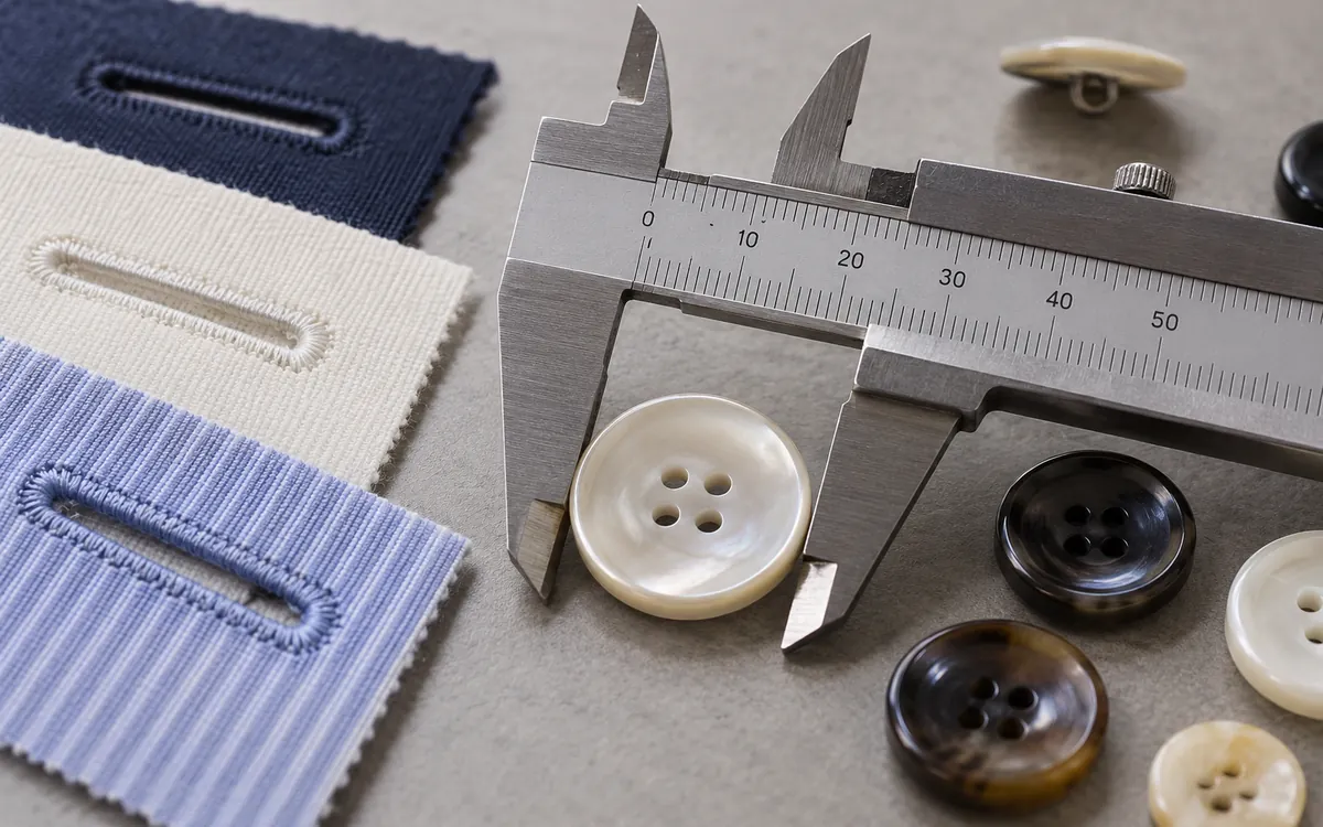
When someone reports a “16 mm buttonhole,” ask what was measured. They may mean the machine setting or cut length. Others may use the distance between bartacks or outside length of the sewn shape.
These measurements are related, but they are not interchangeable. Stitches and bartacks can reduce the free opening. A knife may not cut exactly to the visible ends. Loose fibres or an incomplete cut can make passage harder.
JUKI’s LBH-1790AN catalogue distinguishes cutting knives, sewing dimensions and machine configurations. It also describes a multiple knife-dropping function on relevant models. Machine capability must be checked against the exact configuration in use.
On the specification, name the dimension and show its endpoints. For a functional check, record the actual open passage after sewing and cutting.
If the buttonhole is enlarged to solve difficult passage, recheck security. A closure that is easy to fasten can also become too easy to release. The useful setting lies within a functional range, not at the largest opening the fabric can hold.
Run a focused button-and-buttonhole trial
Make trial pieces from the actual placket, cuff or waistband construction. Include the intended shell, reinforcement, lining and seam arrangement.
Use several trial opening sizes around the proposed starting point. Keep the button, sewing settings and material stack controlled. This lets the team interpret the result.
A hypothetical trial uses a 15.2 mm round button in a reinforced shirt cuff. The team compares three finished cut lengths.
Trial | Finished cut length | Observed result before care |
|---|---|---|
A | 16.0 mm | Button needs force and catches at one end |
B | 16.8 mm | Smooth passage and acceptable retention |
C | 17.6 mm | Easy passage but loose appearance under movement |
These observations concern the trial. They do not link all 15.2 mm buttons to 16.8 mm openings. They identify a candidate for this material and construction.
Repeat the promising trial across more than one piece. Check both opening and closing. Then assess the relevant care route before finalising the dimensions. One sample may work when handled with care. That is weak support for a production decision.
Look at the closed garment, not only the sample strip
A closure can pass a hand test on a flat strip yet fail on the wearer. Position and local tension change the loading.
Check whether the button line follows the intended centre line when closed. Look for twisting, puckering, gaping or the edge rolling away from the button.
At a cuff or waistband, test the planned range of adjustment. A second button position can change how much fabric overlaps beneath the button. The same shank clearance may not behave identically in both positions.
For a jacket front, inspect the button under the expected drape. A heavy button can pull a soft fabric even when the opening fits well.
Include use conditions that matter to the design. Gloves, limited finger access or a narrow cuff opening may make fastening difficult. Record exactly what went wrong. A design change can then address the actual cause.
Use tolerance stacks to choose meaningful trials
The button and opening both vary. Testing only their nominal dimensions can miss an awkward combination.
Assume a hypothetical button diameter range of 15.05–15.35 mm and a finished opening range of 16.60–17.00 mm.
A simple dimensional difference gives:
Smallest opening minus largest diameter = 16.60 − 15.35 = 1.25 mm.
Largest opening minus smallest diameter = 17.00 − 15.05 = 1.95 mm.
This difference is only a screening measure. It does not include thickness, edge shape or fabric flexibility. It can still help select physical samples at opposite ends of the range.
Test the large, thick button with the small opening for difficult passage. Test the small, thin button with the large opening for weak retention. Keep the actual specimens or their measurements with the result.
If either combination fails, identify the dimension causing the problem. Tighten its tolerance or change the design. Do not approve a wide tolerance solely because its average works.
Keep snap sizing separate from sewn-button fit
A snap cap can look like a button, but its closure function comes from a matched assembly. A visible cap diameter is not enough to specify the complete snap.
YKK’s attachment guidance highlights the importance of the foundation. It warns against unsuitable uneven attachment areas. That is a different problem from a sew-through button passing through a stitched opening.
Specify the complete supplier part combination and its intended foundation. Do not substitute a cap, socket or stud based only on a similar diameter or finish.
The same caution applies to tack buttons. Their face size may be expressed in ligne. The attachment system still needs its own matched components and settings.
Keep this distinction visible in the bill of materials. “24L button” leaves room for confusion. One team may mean a sewn button. Another may mean a mechanically attached fastener.
Check performance beyond the size chart
Size checks do not prove resistance to impact, heat or care. Select tests that answer the expected failure question.
ASTM D5171-15(2025) covers impact resistance of plastic sew-through buttons. Its scope is limited. It does not test every button material or attachment. ASTM also discusses the effect of heat during pressing. A button can pass impact testing yet fail at that stage.
That distinction helps prevent overclaiming. A passing impact result applies to impact. It does not prove attachment strength, colourfastness or suitability for every press setting.
Assess the assembled closure after the intended garment care route. Look for a changed opening, cracked buttons, loose attachment, surface damage and reduced function. Where formal tests are required, use the buyer’s agreed procedures and limits.
Do not invent one universal pull force or wash count for all garments. The product, user, market and intended service determine what evidence is needed.
Troubleshoot by symptom
Symptom | First points to examine |
|---|---|
Button catches while passing through | Actual cut length, incomplete cut, thickness and edge profile |
Button releases too easily | Opening size, local stretch, small-button tolerance and orientation |
Button sits on a ridge | Local fabric stack and shank clearance |
Sewing needle contacts the button | Hole pitch, clamp position, feeding and button orientation |
Thread breaks at a hole | Hole-edge condition, thread path and attachment settings |
Button cracks during finishing | Material, impact exposure and the actual heat-pressure route |
Garment front twists when fastened | Position, overlap and local tension |
Do not change several dimensions at once. For example, the team may enlarge the opening and change button thickness at once. It then becomes hard to tell which change solved the problem.
After a fix, repeat the failed condition. A closure that improved on a flat sample may still fail at the thick cuff seam that caused the complaint.
Write a compact functional specification
The final record should identify the button model, material, colour and finish. Add nominal ligne and the controlling dimensions in millimetres.
For a round sew-through button, list diameter, thickness and hole details. Add any important edge profile. State the measurement method and tolerances that the supplier has agreed to meet.
Link this part specification to the closure trial. Record the garment location and material stack. Define the finished buttonhole, attachment route and tested care condition.
Use ApparelDiary’s garment trim approval process for the wider release and substitution controls. The button record should make geometry and function clear. The team can then assess a replacement without guessing.
Frequently asked questions
How many millimetres is a 20L button?
The direct conversion is 20 × 0.635 = 12.70 mm. Check the supplier drawing for the actual nominal dimension and permitted tolerance.
Can I round a measured button to the nearest ligne size?
You can use that result to identify a likely size family. For replacement or production approval, keep the measured dimensions. Confirm the supplier’s model, too.
Does ligne include thickness?
No. The usual button-ligne size describes the face dimension. Thickness and the rear attachment features need separate dimensions.
Can two buttons with the same ligne need different buttonholes?
Yes. Their thickness, edge shape and attachment clearance can differ. The actual garment construction also changes passage and retention.
Is the knife size the finished buttonhole size?
It may be one input, but it is not a complete functional description. Confirm the sewn shape, finished cut and free passage on the actual sample.
Turn a size label into a working closure
Correct ligne conversion prevents a basic purchasing error. Define the geometry as well. Test the assembled product to check that the closure works reliably.
Keep the size family, actual measurements and tolerances separate. Then prove the button with its opening, attachment and care route. This gives the factory a specification it can make and gives the wearer a closure that works.
References
Polkom: Button sizes in ligne and millimetres
Plassan Button: Ligne conversion and size guide
New Mexico State University: Machine buttonholes
JUKI: LBH-1790AN buttonholing machine specifications
YKK: Fastening catalogue and attachment guidance
ASTM: D5171 impact resistance of plastic sew-through buttons

Discussion0
Loading the discussion…