
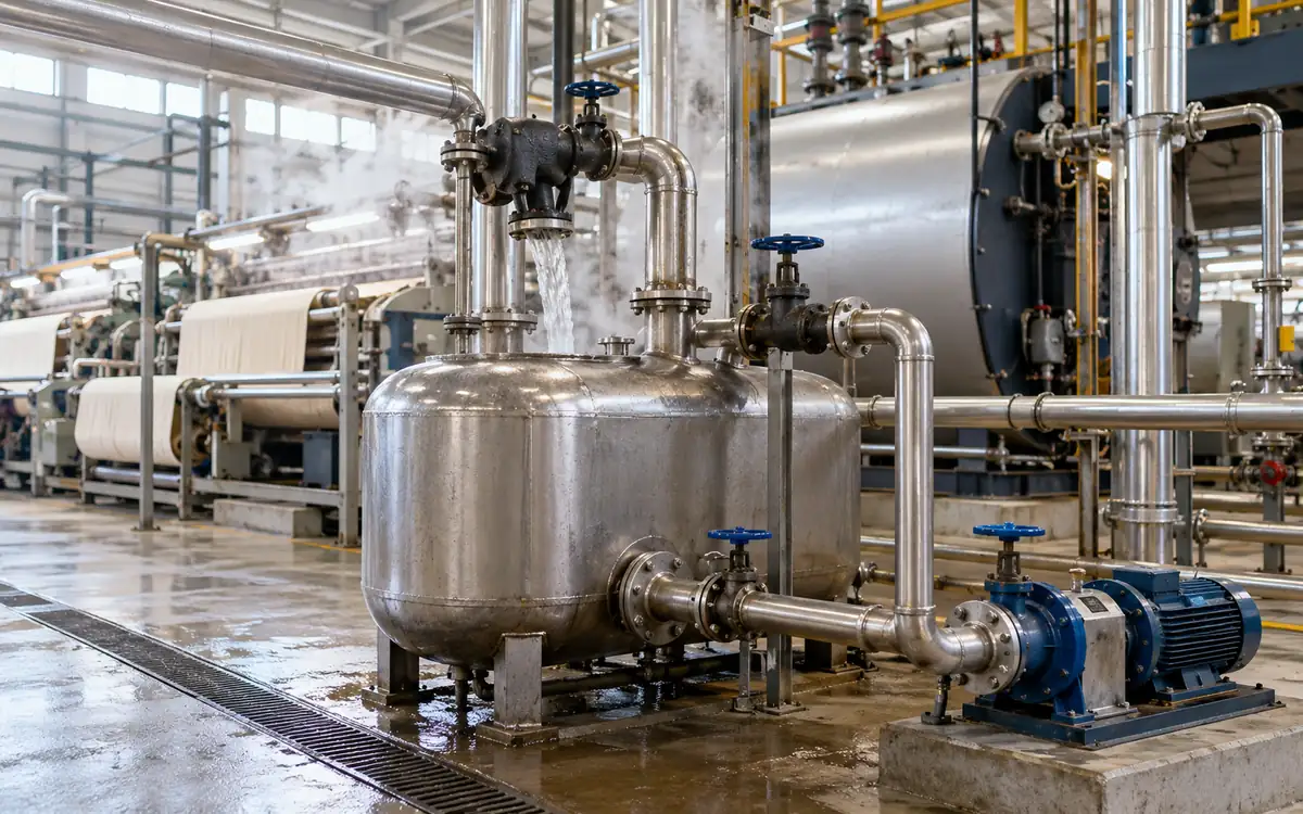
Start with the condensate that can safely return
Condensate recovery can reduce both fuel use and fresh-water demand in a textile mill. Ask how much clean, hot water reaches the boiler feed system. How much water does it replace? The plant would otherwise have to buy, treat, and heat that water.
The answer is rarely the total steam flow. Steam injected directly into a bath becomes part of that bath. An indirect heating coil has a separate condensate route. Its water may be suitable for return. A leaking coil can change that judgement. Water loses some heat before it reaches the feedtank. Flashing, pipework, and vents can all contribute.
A sound project therefore starts with a water balance and a quality decision. It then adds a heat balance, checks the return route and prices only the costs that will change. The DOE condensate-return guide lists several possible benefits. They include lower fuel, makeup water, and treatment needs. They need separate evidence in a factory proposal.
This guide develops those calculations with original hypothetical examples. It concerns a return-network project. Need to size a boiler for peak steam demand? Use ApparelDiary's boiler-capacity guide for that separate decision.
Map steam users before drawing a return main
List each steam-using duty and distinguish direct from indirect heating. Record the condensate route, current destination, and service hours. List process liquids that could enter through a fault. Include small presses and heating coils, not just the largest dyeing machines.
A useful map follows water from the steam user to its final destination. “Returned” should mean that the water reaches the agreed recovery boundary. A pipe label proves little. Check that the receiver pump works and that water reaches the feedtank.
Duty or stream | First recovery question | Evidence to collect |
|---|---|---|
Indirect heating coil | Is the condensate separate from the process? | Coil design, leak history and water tests |
Steam main drainage | Does the route collect clean drainage? | Trap and return-line condition |
Direct steam injection | Where does the injected water leave? | Process balance and bath discharge route |
Suspect or contaminated return | Can it be segregated safely? | Contaminant profile and diversion controls |
Vented receiver | What leaves as water and vapour? | Flow, temperature, vent and overflow evidence |
Do not combine clean and uncertain streams simply to make a larger project. A small, clean return can be useful and dependable. A large but dirty stream may threaten boiler-water quality. Record the reason for each excluded source so that future equipment changes trigger a review.
Define two recovery ratios
The overall return ratio compares returned condensate with steam supplied. It is useful for tracking makeup demand across the plant. The recoverable-stream ratio uses a narrower base. It compares return with condensate from selected indirect duties that can be recovered. It is useful for judging the collection network.
These ratios answer different questions. A plant may use much direct steam injection. Its overall return ratio can be low even when indirect returns work well. Comparing it with a mill that uses mainly indirect heating can be misleading.
Use mass and a consistent period:
Overall return ratio = returned condensate mass ÷ supplied steam mass.
Selected-stream recovery = returned mass from selected sources ÷ condensate formed in those sources.
If the second denominator is estimated from machine records, label it as estimated. Account for flashing, authorised diversion and changes in storage. Do not present all unrecovered water as a leak. A return tank may fill during the test. That stored water has not yet crossed the outlet meter.
Reconcile a simple boiler-house water balance
At steady operation, add exported steam and blowdown to find feedwater demand. Account for any other known losses too. Feedwater comes from condensate return and makeup. This gives a useful cross-check on meter data.
Consider a hypothetical mill with the following hourly balance. Storage is stable, and other losses are assumed negligible for this example.
Mass flow | Before project | After project |
|---|---|---|
Exported steam | 6,000 kg/h | 6,000 kg/h |
Boiler blowdown | 200 kg/h | 200 kg/h |
Required feedwater | 6,200 kg/h | 6,200 kg/h |
Condensate return | 2,700 kg/h | 3,900 kg/h |
Makeup water | 3,500 kg/h | 2,300 kg/h |
The proposed project adds 1,200 kg/h of useful return. With the other terms fixed, makeup falls by the same mass. The overall return ratio rises from 45% to 65% of exported steam.
Suppose 1,500 kg/h of the steam is used directly and 4,500 kg/h serves selected indirect duties. Recovery from those duties rises from 60% to 86.7%. Explain where the remaining 600 kg/h goes. It may leave as flash vapour or through branches and required diversions.
Blowdown is held constant here to isolate the return benefit. Cleaner feedwater may change the required blowdown. Check that with a separate chemistry balance. Adding an assumed blowdown saving at this stage would overstate the evidence.
Measure the water where the benefit occurs
For delivered heat and makeup savings, place the boundary at the feed-system entry. A flow measured near the process may include water later lost from a receiver. A temperature measured at the trap may be far higher than the temperature at the boiler house.
Use paired flow and temperature data across representative operation. One hot reading during a large batch is not an annual average. If return flow changes through the shift, calculate the heat for each interval and add it. The hottest periods may also carry the most water. A simple average temperature can then give the wrong result.
Confirm that a flow meter is suitable for the fluid at that point. Flashing condensate is a two-phase stream. Treating it as a full pipe of liquid can corrupt the measurement. It may be easier to measure liquid after separation. Record all other outlets as well.
Check tank levels at the start and end of a trial. Align the steam, makeup and return records to the same timestamps. Keep overflow and diversion records. A neat balance obtained by quietly changing one meter factor is not a valid measurement.
Calculate the useful heat above makeup temperature
Returned condensate does not replace the entire energy needed to generate steam. Instead, it avoids some makeup heating. The comparison is between the incoming makeup and the return at the chosen boundary.
For a liquid-water screening calculation:
Useful heat rate = mass flow × specific heat × temperature rise.
With flow in kg/h and specific heat in kJ/(kg·K), the result is kJ/h. Divide by 3,600 to obtain kW. For a temperature difference, the number of degrees Celsius equals the number of kelvin.
For detailed work, use specific enthalpy values. Select them at the relevant pressure and temperature. NIST's water and steam tables provide properties based on the IAPWS formulation. Keep one property reference and unit basis throughout the calculation.
The makeup temperature belongs to the water actually displaced. Recovered heat may already warm the makeup. Use its temperature at the correct entry point. Do not give two projects credit for the same preheating. There is only one fuel saving.
Work through the return-project heat balance
Use the hypothetical 1,200 kg/h extra return from the earlier balance. Assume it arrives at 88°C and replaces makeup at 25°C. Take liquid-water specific heat as 4.18 kJ/(kg·K) for this screening example. The annual operating time is 5,000 hours.
Temperature rise = 88 − 25 = 63 K.
Useful heat rate = 1,200 × 4.18 × 63 = 316,008 kJ/h.
Useful thermal power = 316,008 ÷ 3,600 = 87.78 kW.
Annual recovered heat = 87.78 × 5,000 × 0.0036 = 1,580.04 GJ.
The conversion uses 1 kWh = 3.6 MJ, or 0.0036 GJ. This is heat delivered by the return. The boiler's fuel-to-useful-heat efficiency has not yet been applied.
Assume a marginal boiler efficiency of 82%. Use the same heating-value basis for efficiency and fuel price. Then:
Avoided fuel energy = 1,580.04 ÷ 0.82 = 1,926.88 GJ/year.
At a hypothetical fuel price of 9 currency units per GJ, the fuel benefit is 17,341.90 currency units a year. The efficiency is an input to verify at the site. A brochure value may not match how this boiler responds to the project.
Keep the water and operating-cost credits separate
At 1,200 kg/h for 5,000 hours, the extra return is 6,000 tonnes a year. For this cost example, use an approximate cold-makeup density of 1,000 kg/m³. That corresponds to 6,000 m³ of avoided makeup. A final bill calculation should use the site's volume and reference conditions.
Assume purchased water costs 1.20 currency units per m³, excluding treatment. Avoided variable treatment costs are separately estimated at 0.30 per m³. The new return pump uses an average 3 kW during the 5,000 operating hours. Electricity costs 0.12 per kWh. Added annual maintenance is 900 currency units.
Annual item | Calculation | Benefit or cost |
|---|---|---|
Avoided fuel | Unrounded fuel energy × 9 | 17,341.90 benefit |
Avoided purchased water | 6,000 m³ × 1.20 | 7,200.00 benefit |
Avoided variable treatment | 6,000 m³ × 0.30 | 1,800.00 benefit |
Added electricity | 3 kW × 5,000 h × 0.12 | 1,800.00 cost |
Added maintenance | Stated estimate | 900.00 cost |
Net annual benefit | Benefits less costs | 23,641.90 |
With an installed project cost of 47,000 currency units, simple payback is 47,000 ÷ 23,641.90, or about 1.99 years. This is a screening measure, not a full discounted investment appraisal.
Do not add a sewer saving unless the charge actually changes. Do not credit a chemical cost that remains fixed. Include costs for new tests and pump maintenance. Add treatment costs where the return system needs them.
Test the assumptions that can change the decision
The same return quantity is worth less if it cools before arrival. Holding the other inputs fixed, a 70°C return provides a temperature rise of 45 K. Its annual useful heat falls to 1,128.60 GJ, and its annual fuel benefit falls to about 12,387.07 currency units.
The net annual benefit then becomes 18,687.07, giving a payback of about 2.52 years. The project may still be attractive. Its costs and benefits differ from a case based on trap-outlet temperature.
Operating time matters too. At 3,500 hours with the original 88°C return, variable benefits and pumping costs fall with hours. Keeping annual maintenance at 900 gives a net benefit of about 16,279.33 and a payback of 2.89 years.
These tests identify what to measure first. If temperature loss drives the decision, log delivered temperature and examine insulation. If service hours are uncertain, collect production and steam-service records. Improve the input that most affects the result. Extra decimal places will not strengthen a weak estimate.
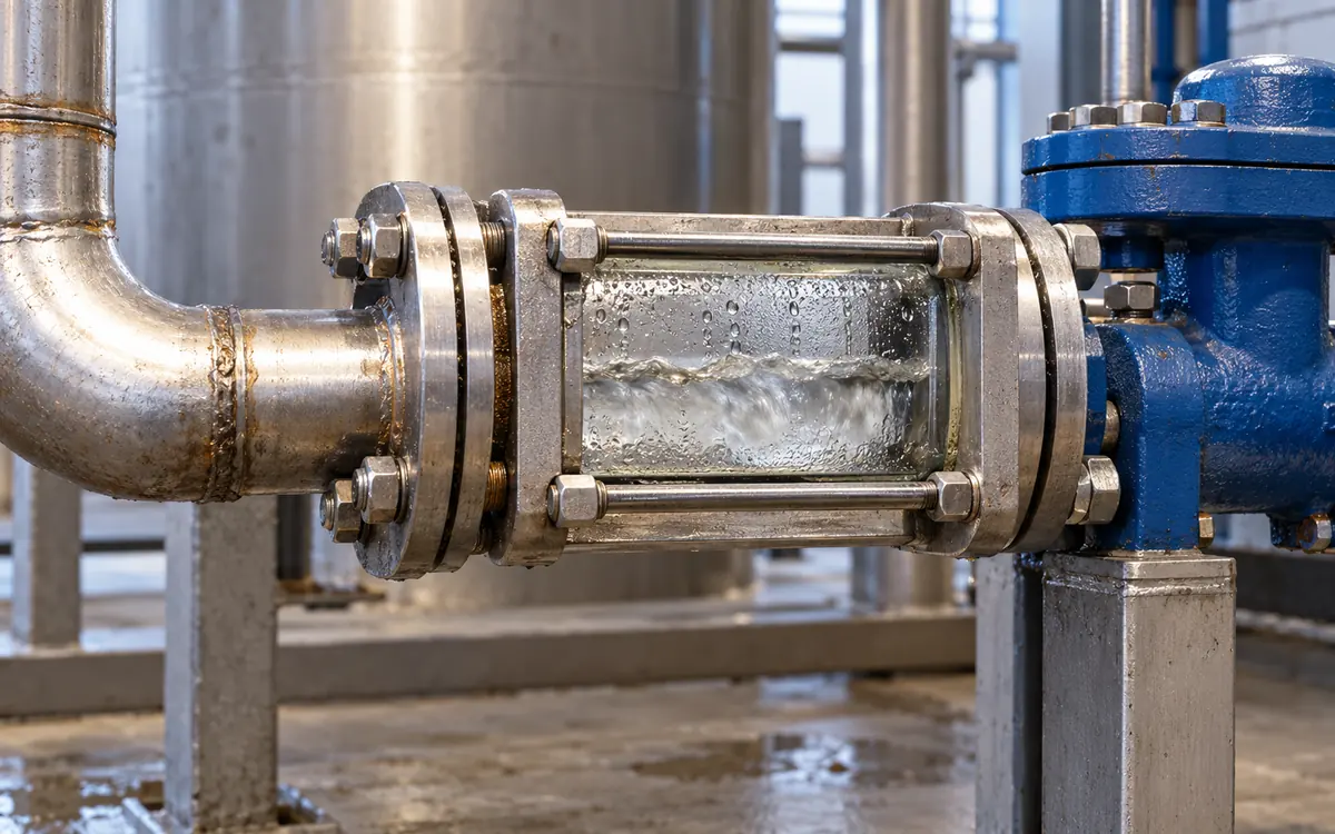
Account for flash steam once
When hot condensate falls to a lower pressure, some may evaporate. An idealised flash calculation is:
Flash mass fraction = (incoming liquid enthalpy − outlet saturated-liquid enthalpy) ÷ outlet latent heat.
For a separate hypothetical stream, assume incoming enthalpy of 640 kJ/kg. Use approximate atmospheric values of 419 kJ/kg for saturated liquid and 2,257 kJ/kg for latent heat. The flash fraction is (640 − 419) ÷ 2,257 = 9.79%. From 1,500 kg/h, that is about 146.9 kg/h of vapour and 1,353.1 kg/h of liquid before other losses.
Spirax Sarco's flash-steam guide explains this balance. It also covers the effect of subcooled condensate. Actual recovery depends on the pressure and temperature of the incoming stream.
Do not subtract flash loss from a return flow already measured as liquid after the receiver. That would count it twice. A separate exchanger may recover flash heat. Record where that heat goes. Count it once, rather than adding it to both the liquid-return and flash-recovery totals.
Match flash heat to a real heat user
A flash vessel does not create a useful heat demand. The recovered vapour needs a suitable user at a compatible pressure and at the same time. An annual total of available heat can hide a large mismatch between supply and demand.
Build a simple time schedule. Compare condensate discharge from the process with feedtank or process-water heating demand. Include periods when the proposed user is already hot. If it cannot take the heat, the system needs an engineered control and disposal route.
A batch machine may discharge hot condensate early. Another process may need warm water only later. Storage can help, but adds heat loss, space, controls and maintenance. Include those effects in the proposal. Do not assume every unit of flash heat will replace fuel.
The Spirax condensate guide separates two heat sources. One is sensible heat in liquid condensate. The other is heat carried by flashed vapour. That distinction helps keep the source and destination balances consistent.
Choose a return arrangement that protects drainage
The return system must accept condensate without causing the heating equipment to flood. Connecting more machines to a common header can change backpressure. Conditions during startup, low load and simultaneous discharge deserve attention.
A vented system collects water in a receiver open to atmosphere. A pressurised system retains a higher pressure and can keep more heat. Its equipment and control needs differ. TLV's comparison describes these tradeoffs. Neither arrangement should be selected solely from its theoretical heat recovery.
The return route must overcome elevation, friction and destination pressure. TLV's pumping guide explains these choices. Trap inlet pressure may drive the return. Other duties need a pump or a combined drainage scheme.
Have the designer check the lowest available inlet pressure, not just the header rating. Check suction conditions for the hot liquid. Review duty and standby needs, access, and what happens if a pump fails. A low fuel bill is not a good result if the recovery project makes production heating unreliable.
Protect the boiler from process contamination
Condensate starts as condensed steam, but its route can introduce contaminants. A damaged process coil, unsuitable connection or dirty receiver can change its quality. Follow the boiler-water treatment plan when deciding what to return. Check the actual risks from each process.
Separate suspect sources where feasible. Define sample points, tests, and acceptance limits. State the alarm response and when return can resume after a fault. Conductivity can reveal some contamination. One reading cannot prove that every contaminant is absent. Choose monitoring that fits the chemicals and failure paths involved.
Spirax Sarco's contamination guidance describes detection and diversion of unsuitable return. The factory must confirm the details with its water-treatment and boiler specialists.
Make diversion visible in the balance. Record how much water is rejected and for how long. Do not bypass a protective diversion because it reduces the reported return ratio. Measure safe, usable return. A large flow towards the boiler house is not enough.
Write a commissioning test around delivered performance
Agree the acceptance test before equipment arrives. Define the sources and operating conditions. State the minimum useful return, delivered temperature range, and required water quality. Include the response to pump failure, high receiver level and contamination alarms.
The test should cover normal production and the states that challenge the design. These may include startup, overlapping batch discharges and low heating demand. Record machine schedules. A later reviewer can then compare the test with the promised duty.
Reconcile the return, makeup and feedwater totals over the same period. Explain tank-level changes. Check the thermal calculation from measured return temperature and the actual makeup condition. Confirm that the added electrical load is included in the benefit calculation.
Use the factory utility load register to record the new pump, controls and utility interfaces. Keep the completed drawings and alarm response with the operating team. Recovery depends on those day-to-day controls after the project team leaves.
Give operations a practical ownership plan
Name the person responsible for each receiver, pump and quality alarm. A shared return network often crosses departmental boundaries. Production may own the steam user, utilities the pump, and the laboratory the water test. The handover must explain how these roles connect when a fault occurs.
Agree what happens during planned shutdowns. Some sources may stop while others continue to discharge. A nearby department may stop work while the receiver still runs. Keep its safe operating arrangements in place. Include these states in operating instructions and shift handover.
Keep a few daily records. Track useful return quantity, delivered temperature, diversion time, and unexplained makeup changes. Use them to trigger investigation, not to punish a team for protecting water quality. A dirty return may need to be rejected. Record both the avoided risk and the lost recovery opportunity.
Make spare-parts and service needs part of the installed cost. A project that depends on an unavailable seal or sensor can spend months out of service. Ask the supplier to identify critical parts and suitable service access. Keep the details needed to order the right replacements. These details affect the hours available for recovery. They also affect the cost case.
Diagnose a project that underperforms
If return mass is low, first confirm that the expected machines actually ran. Then trace diversions, overflows, failed pumps and branches that were never connected. A production change can explain the difference without any equipment fault.
If mass is correct but heat recovery is low, compare temperature along the route. Check long bare pipes and unnecessary storage. A leaking cooling connection can also reduce delivered heat. Check that temperature sensors read the flowing liquid rather than an unrepresentative surface.
If makeup does not fall as expected, review the complete balance. Steam demand, blowdown, storage and other water losses may have changed. If fuel does not fall, check output, fuel properties, and boiler operation. Then review the recovery calculation.
Investigate repeated contamination by source. Mixing all returns before the only monitor may protect the boiler but make the fault hard to locate. A branch record helps locate the cause. It can avoid wasting clean condensate from other sources.
Questions to resolve before approval
Can all condensate be returned?
No. Directly injected steam, contaminated streams and unsuitable drainage routes need separate treatment. Establish a justified recoverable boundary and protect boiler-water quality. Do not set a universal return-percentage target without understanding the process mix.
Does hotter return always make the project better?
Hotter return carries more heat relative to makeup. The receiver, pump, and feed system must be able to handle it. Heat without a suitable destination can create operating problems. Evaluate the complete route and the equipment limits.
Should the proposal use boiler efficiency or combustion efficiency?
Choose an efficiency that reflects the fuel response to displaced heat. State the heating-value basis. A flue-gas analyser's combustion figure does not automatically include every boiler-system loss. Explain the chosen assumption and test it in sensitivity analysis.
What is the best first measurement?
Measure return mass and temperature through normal production. Record makeup use and tank levels at the same time. These readings show what reaches the chosen boundary. That is where the proposed benefit must occur.
Approve a recoverable resource, then verify its use
A sound condensate project needs three forms of evidence. Confirm safe water quality and dependable delivery. Then confirm that the heat user can accept the return. A reconciled mass balance shows the water benefit. A temperature or enthalpy balance shows the heat benefit. A cost model then translates those results into avoidable spending.
Keep each boundary explicit, count flash effects once and preserve the operating assumptions. These details support the investment case. They also make it possible to test the result after installation.
References
DOE: Return Condensate to the Boiler.
NIST: Thermodynamic Properties of Water, NISTIR 5078.
Spirax Sarco: Introduction to Condensate Recovery.
TLV: Vented and Pressurised Condensate Recovery.
Discussion0
Loading the discussion…