
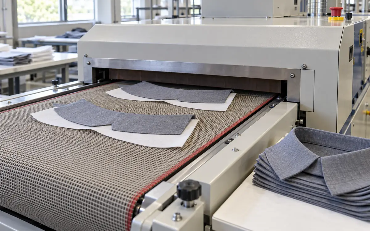
A press may use the supplier’s suggested temperature. That alone does not prove that the bond is suitable. The adhesive may not reach that temperature. A thick material stack may heat slowly. A cold area may exist across the belt. It can produce weak parts beside acceptable ones.
Fusing process validation checks the actual machine. It establishes how that machine can produce the required composite. Start with an identified shell and interlining. Measure the conditions that matter. Check the bond, appearance and shape they produce.
The aim is a usable operating range. One attractive sample made under one setting is not enough evidence for a full production run.
Fix the material and construction first
Begin with the shell and interlining combination selected for the garment. Record their product codes, lots, colours, directions and relevant finishes.
State which side carries the adhesive and which shell face will contact it. Keep the intended interlining shape and coverage visible in the trial record.
Define the loading arrangement. One shell and one interlining form a single pair. Several stacked pairs create a different heating problem. A setting proven for a single pair cannot automatically validate sandwich loading.
Also identify any overlapping support layers. Double reinforcement creates a thicker region. Its heat path and pressure contact may differ.
This article assumes that the material combination is a credible candidate. Check whether a practical setting gives a sound bond and acceptable fabric. If none does, return to material selection. Do not keep raising the press settings. They cannot make every shell and adhesive work together.
Define the result before adjusting the machine
Agree what the fused part must achieve. Include bond performance and face appearance. Check dimensions, hand and shape after the relevant care.
Name the test method for each measurement. State how the result will be reported. State whether limits apply to each specimen, a mean or another defined result.
Use an unfused shell reference for appearance and dimensional comparisons. Keep an approved garment component if its shape or hand is part of the decision.
Do not let bond strength become the only response. A setting may give higher peel force. It may also cause shine, visible adhesive or unwanted stiffness.
Wendler’s fusing guidance stresses the balance between temperature, pressure and time. It names incorrect conditions as a possible cause of poor bonding. Unsuitable material combinations can also be a cause. That balance must be checked on the actual part.
Distinguish three temperature readings
Separate three readings. One is the controller setpoint. Another is belt or platen surface temperature. The third is temperature at the adhesive interface.
The setpoint tells the controller what to regulate at its sensor. A surface reading describes the location and moment measured. The adhesive interface is where the bond must develop.
Heat must pass through the material stack. The interface may heat more slowly than the surface. This matters during a short exposure. Different loading arrangements can change that lag.
Record each measurement with its location. A record may say “Temperature: 145°C.” Where was it measured? It may come from the display, exposed belt or a sensor between the materials.
Segmented heating adds another detail. OSHIMA’s OP-900/1000 information describes separate heating control and a pneumatic pressure system. A multi-zone press needs a setting record for each relevant zone. One unexplained number is not enough.
Use temperature indicators for the question they answer
An indicator can show whether a chosen spot reached a threshold. Select one suited to that task. Check its range and accuracy. Follow its storage and contact instructions.
SpotSee’s Thermax data sheet describes irreversible labels. They keep a record of the highest temperature reached. Such a label does not provide a continuous temperature-versus-time trace.
A label may change at one threshold but not the next. Within its stated performance, this places the result between those thresholds. It does not justify reporting an exact temperature between the two marks.
The decision may depend on heating rate or time above a temperature. If so, use a suitable recording method. It must be approved for the machine and materials. A peak-only indicator cannot answer that question.
Place sensors or indicators at the intended interface. They must not create a gap that changes the test. Follow the equipment and indicator instructions. Keep them out of saleable garments. Account for every test item after the trial.
Calculate dwell time from the right distance
For a continuous press running at a steady belt speed:
Time in a defined zone = zone length ÷ belt speed.
If length is in metres and speed is in metres per minute:
Dwell time in seconds = 60 × zone length ÷ belt speed.
Consider an example effective heating zone 1.20 m long. Belt speed is 4.80 m/min:
Dwell time = 60 × 1.20 ÷ 4.80 = 15 seconds.
At 6.00 m/min, the same zone gives 12 seconds.
Use the actual zone being discussed. Some conveyor areas may provide less heat or pressure. The full length includes those areas. Dividing total machine length by speed can overstate the relevant exposure.
Zone dwell is not always time at the required adhesive temperature. The composite needs time to heat. A recorded interface profile can reveal that difference.
Verify the machine’s time controls
A displayed time may be derived from belt speed or a fixed machine geometry. Confirm what the manufacturer means by it.
Hashima’s HP-450M/MS specification lists belt speed and heating-time capability separately. These figures describe the equipment. They are not a recipe for every interlining.
For a belt machine, check actual travel using a safe, approved method. Do not reach into a moving press or add loose markers that could enter the mechanism.
For a flatbed press, identify the time under the intended contact conditions. Keep it separate from the total cycle. Loading, closing and opening may be outside that period.
Maintenance or control changes may affect travel or timing. Repeat the check after such changes. A recipe tied to “dial position four” is difficult to transfer or verify. Record an actual speed or validated time basis alongside the operator setting.
Understand what the pressure gauge measures
A pneumatic gauge often reports air pressure in a circuit. It does not show the pressure on each square centimetre of fabric.
Air pressure becomes force through the machine’s parts. Cylinder area, linkage, rollers and contact shape affect that force.
Consider a simple example of a direct cylinder. Its effective area is 0.002 m². Air pressure is 0.30 MPa:
Force = pressure × area.
Force = 300,000 N/m² × 0.002 m² = 600 N.
This calculation ignores friction, linkage and other machine effects. It shows the limit of an air-pressure reading. That reading alone cannot describe fabric contact.
Consider a flat contact area of 0.040 m². Assume a uniform force of 2,000 N. The calculated average pressure is:
2,000 ÷ 0.040 = 50,000 Pa = 50 kPa.
A roller nip does not have that same flat contact geometry. Do not apply the example directly to a roller press.
Confirm contact across the working area
Ask the machine supplier how pressure is specified and checked for that model. Keep the units explicit. Line force, total force and pressure per area are not interchangeable.
A worn roller, damaged pad or uneven stack can change local contact. A correct gauge reading cannot rule those problems out.
Hashima’s HP-600LF/LFS information describes pressure rollers and other features. It includes adjustments for material thickness. These details show why the actual setup needs validation.
Use an appropriate approved contact-check method when mapping the press. Pair the machine check with bond specimens from relevant positions. An even-looking contact pattern is useful evidence. The final composite must still meet its requirements.
One edge may repeatedly give weak bonds. Check the machine and loading pattern first. Do not immediately raise the setting across the whole width. The centre may already be near the shell’s damage limit.
Map the belt under realistic loading
A temperature check on an empty machine may not represent production. The material load absorbs heat. It can change the conditions for pieces that follow.
Let the machine reach a stable condition. Then run the intended loading pattern. Include the normal spacing, orientation and number of parts across the belt.
Place identified test specimens at useful positions across the width. Repeat these specimens over time. One row across the belt does not represent the whole process.
Consider an example target of 128–134°C at the interface. A check finds 127°C at the left, 133°C in the centre and 126°C at the right.
Average = (127 + 133 + 126) ÷ 3 = 128.7°C, approximately.
The average lies within the target range. Two positions do not. Averaging across the belt would hide the cold areas.
These temperatures are teaching values, not a recommended fusing range. The point is to evaluate each relevant position against the validated condition.
Design a trial that can explain the result
Start from the interlining supplier’s proposed range and the shell’s known limits. Choose trial settings that are safe for the machine and credible for the materials.
Explore temperature and time while keeping pressure, loading and cooling controlled. Change the latter only if the plan deliberately studies their effects. Record any change.
Include repeated independent runs. Several peel strips from one fused panel describe that panel. They do not fully show how the result varies between cycles.
A practical development trial can first locate a promising region. A later confirmation can examine its boundaries, machine positions and repeatability.
Do not let every new setting also follow more machine warm-up. Plan the order of the trial. That can confuse the effect of the setting with the effect of time. Use a planned order and repeat a reference condition where useful.
The goal is to learn which conditions produce acceptable parts consistently. It is not to find the highest possible number on a force gauge.
Worked example: strength and appearance can disagree
The following example trial keeps pressure, materials and loading fixed. Each row summarises a trial condition. The force values use the same defined specimen width and test procedure.
Condition | Measured interface temperature | Zone dwell | Bond result before care | Bond result after care | Face appearance |
|---|---|---|---|---|---|
A | 120°C | 12 s | 3.2 N/25 mm | 1.5 N/25 mm | Acceptable |
B | 128°C | 15 s | 5.4 N/25 mm | 4.6 N/25 mm | Acceptable |
C | 136°C | 18 s | 6.1 N/25 mm | 5.0 N/25 mm | Visible shine |
D | 128°C | 12 s | 4.9 N/25 mm | 3.2 N/25 mm | Acceptable |
Assume this project requires at least 4.0 N/25 mm after care and no visible shine. These invented limits apply only to the example.
Condition C gives the highest force but fails appearance. Conditions A and D fail the stated after-care requirement. Condition B is a promising candidate.
That does not yet establish an operating window around B. Repeat it and test nearby conditions. Include relevant machine positions and material variation. Confirm that the apparent success is reproducible.
Interpret bond-force results on their own basis
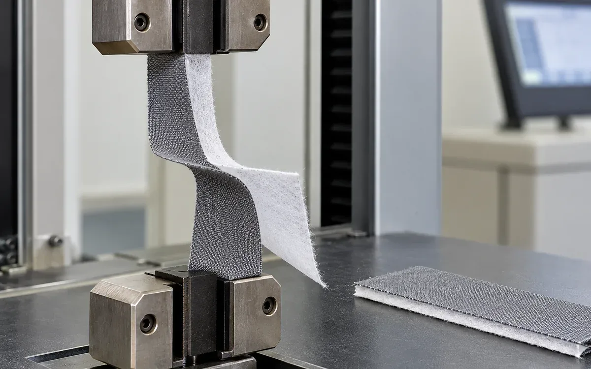
ASTM D2724 provides a bond-strength method for bonded, fused and laminated apparel fabrics. Tests can take place before or after laundering and drycleaning.
Use the complete agreed procedure for formal results. Define specimen width, direction, preparation and reporting basis through that method.
The table reports 4.6 N per 25 mm. As force per width, that equals 1.84 N per 10 mm:
4.6 ÷ 25 × 10 = 1.84.
That arithmetic does not authorise changing specimen width in the physical test. Width and edge effects can influence the measured result. Check the methods and specimen shapes. Compare actual tests only when those conditions support it.
Record how failure occurs. Separation at the adhesive interface is different from tearing the shell or support. The substrate may fail before the bond separates. That result is not a simple measure of adhesive failure.
Keep individual readings when the acceptance rule requires them. A mean can conceal a weak edge or a poorly fused specimen.
Make cooling part of the route
A part may still be soft as it leaves the heated zone. It may distort easily. Define its support during cooling. State when staff can move, fold or stack it.
Use the supplier’s guidance for the material and the machine’s approved cooling arrangement. Do not transfer one product’s cooling time to every interlining.
Wendler identifies insufficient cooling among the possible contributors to later bonding problems. A trial may cool flat on a bench. That differs from production where hot parts are bent straight into a stack.
Observe the actual exit handling. A part may leave the press flat. Pulling it from the belt or dropping it onto a narrow support can distort it.
Record cooling and handling in the validated route. If these steps are missing, operators may change them. They may still believe the fusing route is unchanged.
Test the full intended care exposure
A strong initial bond can weaken after care. Keep initial and after-care results as separate evidence.
Use the agreed garment-care or laboratory route. Include drying and any further finishing that forms part of the specified exposure.
For Condition B in the example:
Retained force = 4.6 ÷ 5.4 × 100 = 85.2%, approximately.
This percentage describes the change in the two reported results. It does not replace the project’s absolute after-care requirement.
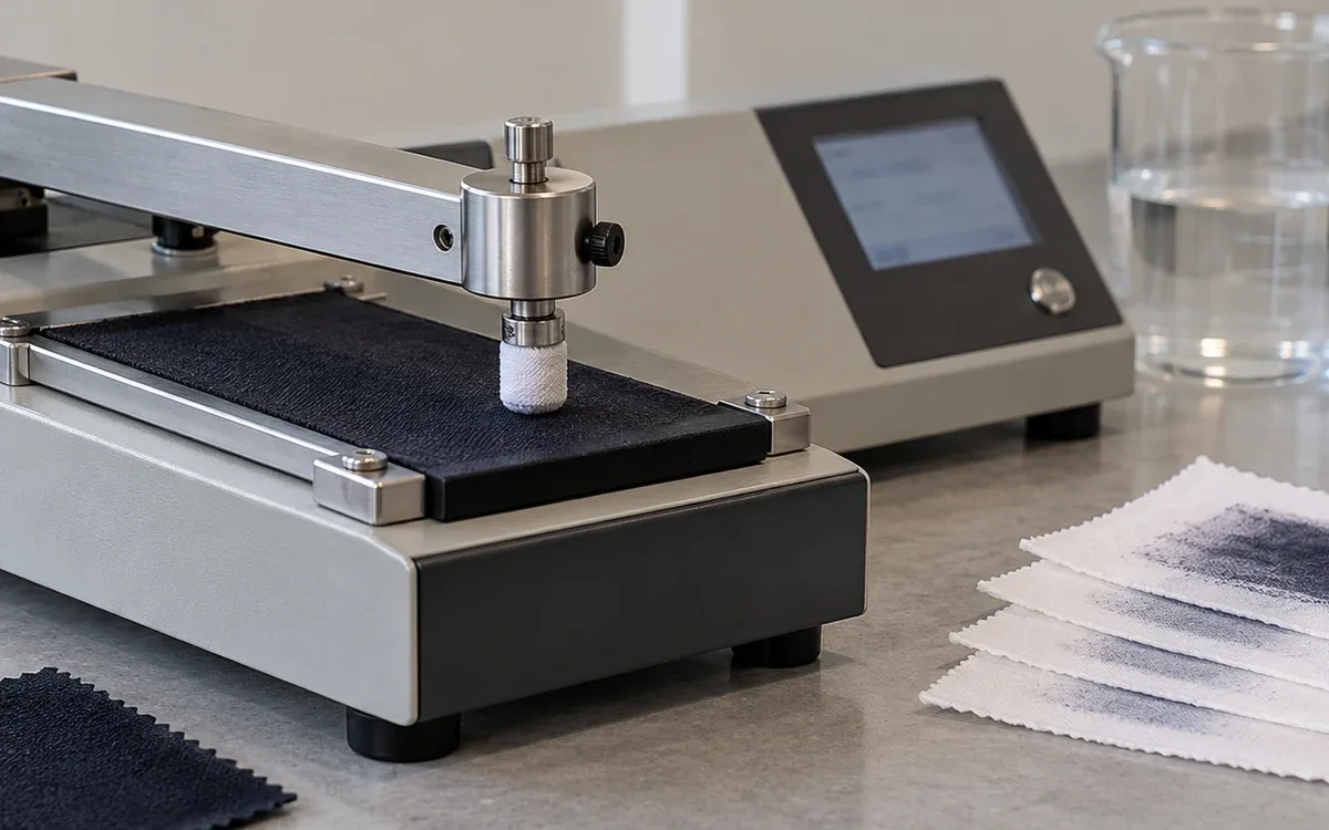
Also inspect bubbles, edges, face marks and dimensional change. A local area may visibly lose its bond. Strips from elsewhere can still give acceptable force.
Keep an untreated reference and identify the exact care sequence. A note may say only “wash passed.” Another factory cannot reproduce or assess that result.
Distinguish strike-through from strike-back
Adhesive may appear at the shell face. It may reach the interlining’s reverse side instead. These are different observations. Name the side and location rather than recording only “glue problem.”
Wendler’s guidance links these defects to the material structure and processing conditions. It also identifies belt contamination as a possible source of adhesive residues.
Inspect an unfused control and run a clean-machine trial. These help separate material migration from dirt or adhesive already on the belt.
Do not assume that more pressure will cure a weak bond. It may push adhesive into an unwanted area or change the shell appearance. A lower temperature may hide visible adhesive. The bond may then be too weak.
Change one suspected cause in a controlled comparison. Then check both adhesion and appearance again.
Control loading orientation and stacking
Show which layer faces each heated surface. State the part spacing and whether stacking is allowed.
Changing orientation can change the heat path. Adding another pair of materials can alter both heating and contact. Sandwich loading may raise output. It is useful only if every layer remains acceptable.
Identify specimens from the top, middle and bottom of a proposed stack where relevant. Do not combine their results into one average before checking each position.
Check for unintended bonding between adjacent pieces. Adhesive migration can cause layers to stick where the construction does not require it.
Keep loading instructions simple enough to use at the machine. Add a clear sketch to the work instruction. It can prevent errors caused by a complex written description.
Do not approve repair by repeated pressing alone
A second pass may improve a weak bond. It also adds heat and mechanical exposure. It can change shade, shrinkage, hand or the behaviour of the adhesive.
Treat re-fusing as a separate route that needs evidence. Identify the original conditions that made the affected parts. Check whether the material can tolerate another pass.
Compare repaired specimens with correctly fused controls. Assess the relevant care performance as well as the immediate result.
Track which pieces received one or two passes. Without that identity, the repair record is unreliable. Keep the affected quantity and treatment history clear.
Repeated pressing should not become an informal way to compensate for an unstable machine. Correct the cause and validate the normal route.
Translate the window into a production recipe
The released recipe should identify the machine, materials and loading. Add zone settings, verified speed or dwell basis, pressure setting and cooling route.
Include the measured conditions that justified those controls. The recipe can then be checked after maintenance. It can also guide fresh validation on another machine.
Define startup and restart checks. Long idle periods, power interruptions, belt replacement or heater work can change the process state.
Set a practical monitoring frequency. Base it on the process and the effect of drift. Check more closely while stability is being established. Do not claim one fixed interval suits every press and product.
Use ApparelDiary’s garment trim approval process to connect the validated material use with bulk release. The machine record should show how the factory will control the process. Keep it within the proven conditions.
Keep output targets inside the validated route
A faster belt changes dwell time. Closer spacing changes loading. Extra layers change the heat path. Each can affect the result.
For a hypothetical belt speed of 4.8 m/min and row pitch of 0.45 m:
Rows per minute = 4.8 ÷ 0.45 = 10.67, approximately.
If two parts fit across each row, the geometric feed rate is about 21.3 parts per minute.
That is not a guaranteed accepted-output rate. Loading, cooling, inspection and the validated thermal response can limit production.
If the required volume exceeds the proven route, change the production plan or validate a revised route. Faster speed may seem to help fusing output. Without bond checks, it can move the loss to later sewing or customer care.
Troubleshoot from the pattern
Pattern | Focused checks |
|---|---|
Weak bonds on both belt edges | Temperature and contact across the width |
Weakness after a fast restart | Thermal recovery and startup procedure |
Good initial bond, poor care result | Material compatibility, actual conditions and care exposure |
Shine only on heavier overlaps | Local heat, pressure contact and layer thickness |
Random adhesive marks | Belt cleanliness, part edges and handling |
Curled parts after exit | Cooling support, layer change and exit handling |
Different results from the same displayed recipe | Sensor basis, speed, loading and machine condition |
The pattern narrows the investigation. It does not prove the cause. Confirm a proposed explanation through a controlled change and a repeated result.
Frequently asked questions
Is the displayed temperature the adhesive temperature?
Not necessarily. Measure the relevant interface with a suitable method and record how it relates to the controller setting.
Can a temperature strip prove the full heating profile?
A peak-recording strip cannot show the complete time history. Use it for the threshold question it can answer.
Should the strongest bond setting be selected?
Only if it also meets appearance, shape, hand and care requirements. A higher force does not excuse damaged fabric.
Can the same recipe run on another press?
It is a starting reference, not proof of equivalence. Confirm the new machine’s actual conditions and resulting part performance.
Is a second pass an acceptable repair?
Only after that repair route is assessed and controlled. Another pass adds exposure and may create a different defect.
Validate the process the factory will run
Reliable fusing comes from a defined material combination and measured machine behaviour. Temperature, time, pressure, loading and cooling must work together. Their operating range must protect both bond and appearance.
Prove that range across the working area and through the intended care. Then release a recipe that operators can repeat and technicians can verify. The result is evidence for the production process. One display setting and one sample cannot provide that evidence.
References
Wendler: Fusing conditions and troubleshooting
OSHIMA: OP-900/1000 continuous fusing machine
Hashima: HP-450M/MS compact fusing press
Hashima: HP-600LF/LFS and HP-900LF/LFS press features
Discussion0
Loading the discussion…