
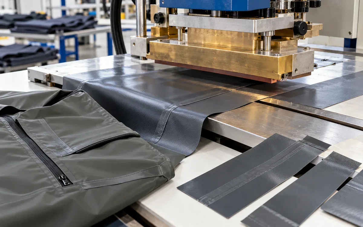
A coated fabric can form a neat weld and still fail in use. The join may peel at a corner, leak through a crossing or weaken after care. HF welding approval links three things: the material, joint shape and machine cycle. Together, they must meet the product’s needs.
HF means high frequency. In this process, an electric field heats a suitable polymer within the joint. Pressure brings the softened surfaces together. The joint then cools while held in place. A useful trial shows that this sequence works as production varies. One attractive sample is not enough.
This guide follows an original example of a coated-fabric garment component. All figures in the worked examples are made up for teaching. They explain how to plan a trial and read its results. They are not machine settings or limits for every product.
Define what the welded joint must do
Start with the part’s job in the finished product. A pocket edge may serve as decoration. A rain barrier must keep water out. A strap join may need to carry a load. List the forces, movement, wet exposure and care that the joint will face. Include contact with other garment parts.
Describe the product claim precisely. “Waterproof seam” needs a defined test condition and an agreed result. “Strong weld” needs a direction, specimen shape and force requirement. A smooth surface is an appearance result. It cannot stand in for either claim.
Consider where load enters the joint. A broad overlap may carry a spread-out pull well. It may still lift easily when a corner catches. A narrow tab may concentrate force at one small edge. Two garment details may use the same material and weld width. Their joints can still behave differently.
Keep the intended construction on a drawing. Mark the overlap, weld path, entry and exit points, corners and any crossing. Identify the face that will contact the electrode. Show nearby folds or hardware that could alter the stack.
ApparelDiary’s guide to garment seam selection helps frame the wider construction decision. The qualification here concerns a particular welded joint and its process evidence.
Confirm that the coating responds to HF energy
HF welding is also called radio-frequency or dielectric welding. A suitable material absorbs energy from the changing electric field. This heats the material within its volume. This differs from simply applying a hot tool to the surface. TWI’s explanation of RF welding describes that heating principle.
The polymer’s response matters. Calling it thermoplastic does not prove that it will weld. TWI identifies PVC and polyurethane among common RF-welded materials. It also explains that other polymers need particular conditions or modified formulations. Ordinary polyethylene and polypropylene should not be assumed suitable for the same process. Check the actual grade and coating system in the TWI material-compatibility guidance.
Request the supplier’s exact material code. Record the base textile, coating chemistry, coating side, thickness range, finish and batch. Two fabrics may both be called “PU-coated polyester.” They can still have differences that affect joining.
Check what sits between the bonding faces. It may be a surface treatment, print, release layer or dirt. Examine the real stack rather than a simplified material description. The construction may need an added film. If so, identify and control that film too.
Start with the supplier’s evidence that the materials can join. Then test the proposed joint on the intended equipment. A trial on a different coating may guide the work. It does not approve the new coating.
Separate material strength from joint performance
The joint can fail in several places. The two fused surfaces may separate. The coating may detach from its textile base. The base fabric may tear beside the weld. A thinned edge may split even though the centre remains bonded.
Record the failure location as well as the measured force. A higher number can hide a change to a less suitable failure mode. A tear just beyond a sharp weld edge may point to local damage. A simple pass mark could hide that clue.
Compare the welded part with relevant unwelded material. This helps establish whether welding changed the surrounding substrate. Do not calculate “weld efficiency” from unlike tests. A peel force and a fabric strip-breaking force use different loading conditions.
Even comparable strength values do not answer every product question. A joint might withstand a short pull. It could open slowly when the load stays in place. Another might hold a static load yet fail when bent repeatedly. Choose the tests from the intended service, then keep each result separate.
The public scope of ASTM D751 covers several coated-fabric properties, including seam-related and water-resistance tests. Use that scope to help choose a method. The lab still needs the full procedure and the buyer’s limits.
Make the joint drawing measurable
A useful drawing states what an inspector can measure after welding. Distinguish the total overlap from the effective bonded width. Material can overlap beyond the edge of the electrode without being fused.
Consider an example joint with a 16 mm overlap. Its intended weld track is 10 mm wide. The remaining material provides positioning space. It does not add another 6 mm of bonded width. The track may shift toward one edge. The total overlap stays the same, but the intended margin may be lost.
Set the measurement locations. A straight portion, a corner and a crossing may need separate checks. State what the width measurement covers. It may follow the visible mark or the confirmed continuous bond. Those features are not always identical.
Give curved joints their own attention. A sharp change in direction can affect how load reaches the edge. Tool shape can also leave narrow regions or pressure differences. A long straight sample tests only part of the shape. Its centre cannot prove that the whole outline works.
Where several welds meet, define their order. A second cycle can reheat an earlier joint. The finished crossing must be checked after the full sequence. Passing separate single welds does not prove the crossing will perform in the same way.
Understand the machine cycle before changing it
A production cycle includes placement, clamping, energy application, cooling and release. The machine may show several settings. These describe its controls. They do not prove that the finished joint works.
TWI’s weld-quality guidance names several factors that act together. These include power, pressure, heat conditions and material thickness. This is why a setting copied from another machine cannot qualify a new construction.
More energy is not always better. A primary study, Process Parameters of High Frequency Welding, tested polyurethane-film joints. Too much energy could reduce their strength. Material thinning and damage at the joint region mattered. Its experimental settings belong to its materials and equipment.
Cooling also belongs to the joining cycle. Forsstrom describes holding pressure during cooling as part of HF welding. Releasing a hot joint early may change the result. Test the complete cycle that production intends to use.
Keep operator adjustments within the machine maker’s instructions. The trial should be run by trained staff who understand the equipment and material. State the approved control ranges in the trial record. There is no single “best temperature” for every coated fabric.
Check tooling and repeated-cycle heating
The electrode helps define the weld’s shape and applies pressure to the stack. Its contact condition therefore deserves the same care as the material specification. Check for damage, dirt and uneven contact first. Do not try to explain every defect through process settings.
Record the tool identity and revision. A repaired corner or replacement insert can change local contact. A tool may look like the original. Check the features that matter to the joint before approving it.
Tool temperature can change during a run. The first cycle after a long stop may use a cool tool. A later cycle with a warm tool may give a different result. Forsstrom’s cooling guidance addresses heat accumulation and temperature control in repeated HF operation.
Include both early and steady-run samples in the trial. Also examine the first pieces after a planned interruption. Keep those groups identified. Combining all samples into one average can hide a start-up problem.
Use the actual production pace during confirmation. Long pauses between lab samples let the tool cool. The production line may never see that pattern of heat and cooling. Keep cycle timing in the trial. A setting that works slowly may become unstable when output rises.
Build a trial that answers a defined question
Begin with a documented baseline supported by the material and equipment suppliers. Choose which factor the next trial will examine. State what remains fixed and what observations will decide whether the change helped.
A focused trial may change the energy applied. Keep the tool, pressure, cooling and material the same. Another may examine cooling time at an established joining condition. Changing everything at once may find a workable combination. It gives little evidence about which change helped.
Include representative material variation. Where the supplier permits a thickness range, test relevant portions of that range. Use the actual coated side and product orientation. Include a second lot when lot-to-lot consistency forms part of the approval question.
Repeat production cycles, not only measurements on one welded panel. Several strips cut from a single panel share one welding event. They show variation within that panel. They do not show whether the machine cycle repeats well.
A proposed record could contain these fields:
Trial field | Why it matters |
|---|---|
Material code, lot and measured stack | Links the result to the actual construction |
Tool identity and joint position | Reveals local and tooling effects |
Machine and approved setting revision | Makes the cycle traceable |
Cycle order and pause history | Exposes warm-up or restart changes |
Sample conditioning and care route | Keeps comparisons on the same basis |
Result and failure location | Shows what failed, not just how much force it took |
Select samples before seeing the results. Retain poor pieces as evidence. A folder containing only the best samples cannot support a reliable process decision.
Read a hypothetical strength trial carefully
Suppose a team compares three approved trial conditions. They label them A, B and C. Five separate weld cycles are tested at each condition. Each result uses the same specimen width, peel geometry and reporting rule.
The project’s hypothetical minimum is 40 N for that defined test. This number is an invented requirement for the example, not an industry threshold.
Condition | Five reported forces, N | Mean, N | Lowest result, N | Observed concern |
|---|---|---|---|---|
A | 36, 39, 41, 38, 40 | 38.8 | 36 | Several weak separations |
B | 46, 48, 47, 49, 45 | 47.0 | 45 | No local concern in this set |
C | 51, 52, 50, 34, 49 | 47.2 | 34 | Thin edge on the low sample |
Condition C has the highest mean. Yet one result falls below the example requirement and has a visible edge problem. Choosing C from the average alone would ignore both pieces of evidence.
Condition B is the stronger candidate for further work in this small trial. It has not automatically earned production approval. The team still needs the other required tests. It must cover relevant material variation and show that the process repeats.
Report the width beside the force. A 25 mm specimen differs from a 50 mm specimen. Reporting both in newtons does not make them comparable. Dividing force by width may help a defined comparison. It does not make different test methods equivalent.
Keep the original values. A mean rounded to 47 N should not replace the five readings or their failure notes. The spread tells a different part of the story.
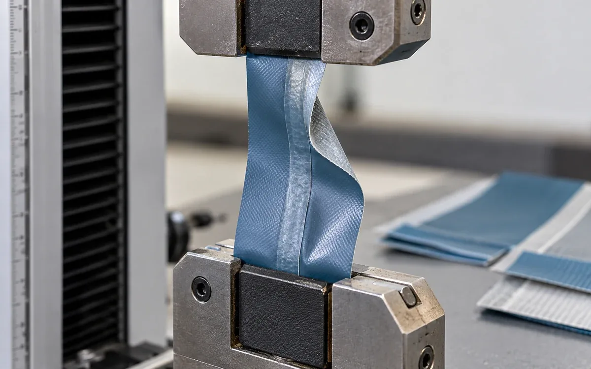
Use several tests for several failure questions
Write a test plan that connects each method to a potential failure. A single “seam test” label is too broad to support a product claim.
Question | Useful evidence to specify |
|---|---|
Will the joined faces separate? | Defined peel or bond assessment |
Will the complete seam carry its service load? | Appropriate seam loading and failure location |
Can liquid pass through the finished detail? | Agreed pressure or leakage assessment of the actual joint |
Does movement damage the edge? | Relevant flexing or repeated-use assessment |
Does care change the construction? | The required care route followed by the relevant checks |
Use fresh specimens where a test damages the sample. A joint already pulled close to failure is unsuitable as an untouched leak specimen. It may still help a study of damaged joints. Label that use in the record.
The shape may affect performance. If so, test the complete feature as well as simple coupons. A coupon is useful for comparing materials and process settings. A coupon may miss risks at a pocket corner or hem crossing. An attachment point may add another risk.
Do not convert an internal water screen into a certified product rating. Keep the screening method, fixture and endpoint visible. Formal claims need the specified method, suitable specimens and an appropriate laboratory report.
Diagnose leaks by location
When a welded feature leaks, mark where water first appears. Preserve the orientation and test setup. A leak may occur beside the weld or through a crossing. It may come from an unsealed opening. Record which one occurred.
Inspect the surface before pulling the joint apart. Record wrinkles, skipped contact areas, local thinning and foreign material. If destructive examination is needed, retain another sample for comparison.
A passing peel result does not rule out a small discontinuity elsewhere on the seam. Equally, a leak does not prove that every part of the weld is weak. Use the location to choose the next comparison.
Consider an illustrative pocket whose straight edges pass the chosen checks. Leakage occurs only where the final closing weld crosses an earlier side weld. Focus the next trial on that crossing. Check the stack, tool contact, joining order and heat history. Raising energy on every straight edge would change regions that already work. It would not address the specific fault.
After a correction, test the complete pocket again. Confirm that the change solved the crossing problem without damaging nearby material. The original failed piece should remain linked to the revised drawing and trial record.
Confirm performance after the required care
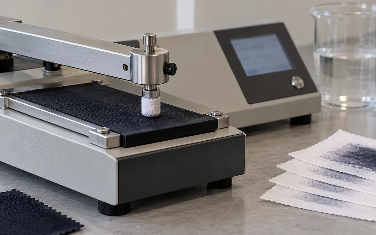
Garments encounter cleaning, drying, storage and handling after joining. Qualification should reproduce the relevant approved route. Keep production treatment distinct from the care instructions intended for the wearer.
Record the exact method and cycle count used for testing. “Washed several times” is not enough to reproduce the comparison. Include the drying stage and the condition in which measurements were made.
Check appearance, bond, dimensions and leakage where each matters. A seam can remain bonded while its coating changes colour. The fabric around it may also shrink. The product decision needs the complete set of required outcomes.
A simple retention calculation can help describe comparable force results. Suppose matched groups average 48 N before care and 42 N afterward under the same test:
Retained force = 42 ÷ 48 × 100 = 87.5%.
The loss is 6 N, or 12.5% of the initial mean. Whether 42 N is acceptable depends on the actual product requirement. A high retention percentage cannot rescue an inadequate absolute result.
The strength test destroys each specimen. Use separate matched groups for the before and after tests. Do not describe the calculation as though one physical strip survived both breaking tests.
Estimate capacity from the whole cycle
The time with HF energy on is only part of output planning. Placement, clamping, cooling, removal and inspection also use time. Some tasks may overlap on suitable equipment. Other tasks need the same station and must take turns.
Consider a made-up job on one station. Placement takes 12 seconds and clamping takes 2 seconds. Applying energy takes 5 seconds. Cooling takes 7 seconds, followed by 4 seconds to remove the piece.
Total occupied time = 12 + 2 + 5 + 7 + 4 = 30 seconds.
The theoretical rate is 3,600 ÷ 30 = 120 cycles per hour. If the observed plan allows 45 productive minutes in an hour, the corresponding rate is 2,700 ÷ 30 = 90 cycles. At a measured accepted yield of 96%, expected accepted output is 86.4 pieces per scheduled hour.
These figures assume one piece per cycle and no overlap. A shuttle tool or multiple-part tool needs a different model. Measure the actual work sequence before comparing machine offers.
Shortening cooling by two seconds would alter the qualified joining cycle. The shorter cycle must pass the required joint checks. Until then, any expected output gain remains unproven. Output and product evidence belong in the same decision.
Make the approved process usable on the floor
The release record should identify the material stack, tool, drawing and machine. Add the control ranges and required start-up checks. Include the sample locations and the evidence behind the decision. Name any restrictions, such as an unqualified crossing or excluded coating lot.
Keep a clear route for changes. A changed coating or repaired tool may affect the joint. An added print or new care route may affect it too. Review the change against the reasons the original construction passed.
Define how production detects drift. Choose checks that suit the process. These may cover early-run samples, track width and joint placement. Add destructive or leak samples where agreed. The frequency should follow the approved control plan and actual process risk.
Use equipment safeguards throughout qualification and production. OSHA’s RF hazard guidance identifies engineering controls such as shielding and suitable separation from exposure sources. Machine guarding, maintenance and RF controls need competent review. A product trial is not permission to bypass them.
When a defect appears, retain the piece and identify the affected production interval. Use the approved process to restore a known condition. Check the result before closing the issue.
Questions teams often ask
Can any waterproof coated fabric be HF welded?
No. Water resistance describes a product property. HF weldability depends on the actual polymer system and joint stack. Confirm the coating grade and its response through supplier evidence and a representative trial.
Does a wider weld always give a stronger garment?
A wider bond may spread the load differently. Width alone cannot predict the finished result. Edge condition, material damage, load direction and geometry also matter. Test the proposed width in the actual construction.
Can a good peel test replace a leak test?
It cannot. Peel testing examines separation under a defined load. Leakage concerns a continuous barrier under a different condition. The product may need both results, particularly at corners and crossings.
Should production use the setting with the highest mean force?
Only if it also meets the other requirements and has a suitable operating range. The example shows the risk of using a high mean alone. It can hide a low result and a damaging failure mode.
When should the process be checked again?
Review changes that affect the material, joint, tool, equipment or service requirements. Recheck also when production evidence shows drift. The extent of the work should match the changed risk and the evidence already available.
Release a construction that can be repeated
A sound approval names the coated fabric and the joint. It defines a welding cycle that can be repeated. It preserves individual test results, their failure locations and the conditions that produced them.
The joint must meet its appearance, load, leakage and care needs. It must do so as normal production varies. A good-looking sample begins that investigation. A clear drawing, controlled trials and complete product evidence finish it.
References
TWI: Materials suitable for RF welding
TWI: Factors affecting RF weld quality
Forsstrom: High-frequency welding
ASTM D751: Coated fabrics, public scope
Rogale and colleagues: Process Parameters of High Frequency Welding, 2024
Discussion0
Loading the discussion…