
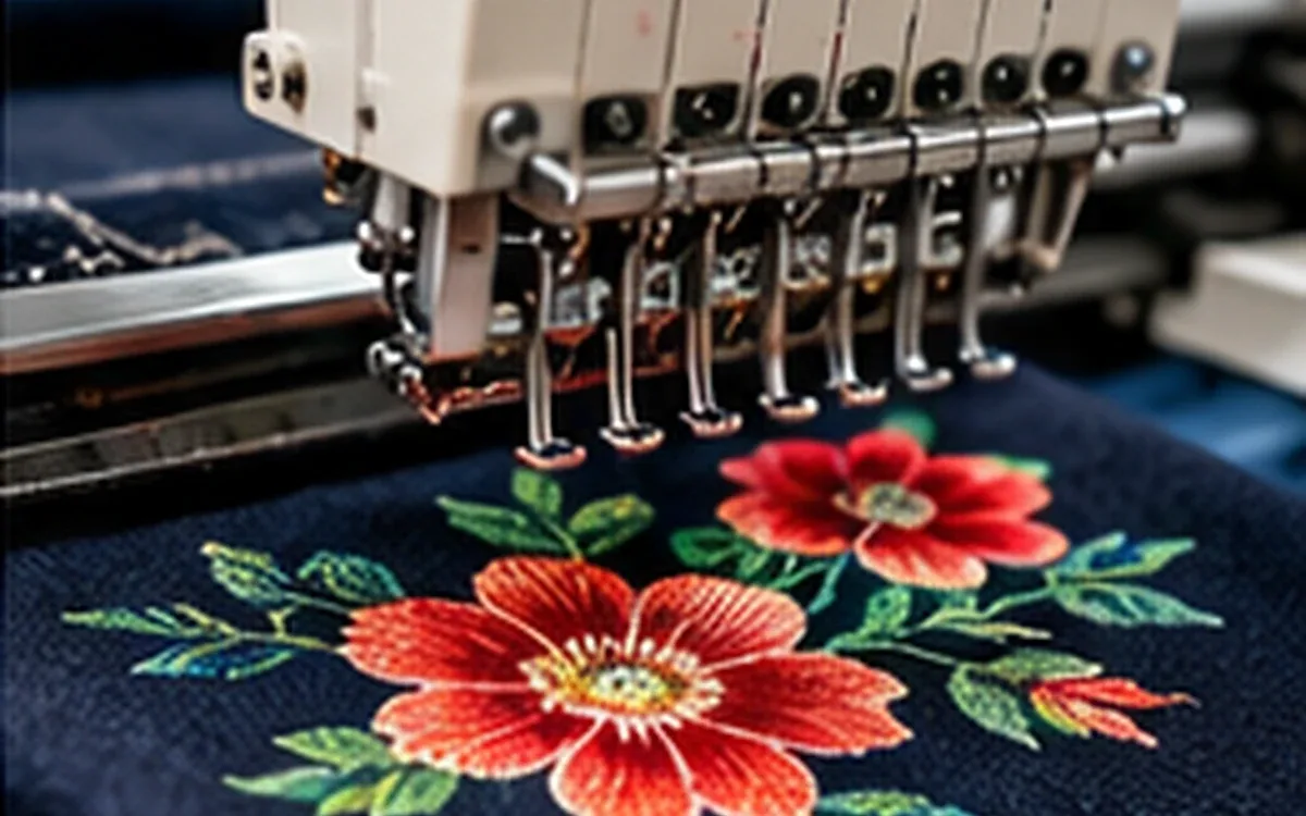
A sewing machine can make a poor seam even when every part is present. The thread may miss a guide. A foot may suit another operation. A control may be set correctly while the wrong bobbin sits below the needle. Knowing each part's name helps, but knowing its job makes that knowledge useful.
The best way to learn sewing machine parts and functions is to follow the work through the machine. Trace the thread from its supply to the stitch. Trace the fabric across the support and feed parts. Then connect both paths to the controls that start, stop and change the sewing cycle.
This guide uses industrial garment machines as its main setting. The examples explain how to identify parts and verify an approved setup. Use the model manual for the thread route and matching parts. It also defines which work is allowed. A familiar-looking machine may have a different control system or stitch-forming mechanism.
Identify the machine before naming its parts
Begin with the full model and subclass on the machine. Add the factory asset number so the record points to one physical unit. Where the control unit has a separate identity, record that too. A name such as “single needle” describes too little to select a manual or order a spare.
Use the maker's parts drawing alongside the operating manual. The drawing helps identify an assembly and its order number. The manual explains how the operator uses it. A number beside an arrow in a drawing may be only a callout. It is not necessarily the number used to buy that part.
Some machines have a pattern selector or stitch-width dial; others do not. A bobbin release button is also a design feature. Those controls depend on its design. A straight-stitch industrial machine may offer no zigzag width control at all. A computer-controlled model may put several settings on a screen.
For example, Juki's DDL-9000C information describes full digital variants. Other versions use springs for thread tension and foot pressure. The family name alone does not define how those settings work. Check the exact version before copying a colleague's setup instructions.
Follow the upper thread from supply to needle
The thread path is a sequence of working contacts. A guide changes the route. A tension device controls resistance to thread movement. The take-up mechanism manages the changing thread demand as each stitch forms. These parts work together, but they are not interchangeable.
Thread stand, spool holder and guides
A stand supports the thread package and guides the thread toward the machine. Industrial cones often remain still while thread draws off their tops. The supply arrangement must suit the package and the machine. A cone, a small spool and a bobbin are different forms of supply.
Inspect the route from the actual package, not just from the first guide on the head. Thread may snag at the package. It may also catch before it reaches the tension device. A&E's thread-breakage bulletin covers thread take-off. It places the stand eyelet above the centre of the cone.
Ask whether the thread can follow its intended route without snagging. Do not copy a stand height from an unrelated machine. Check package size, stand design and the approved thread route together.
Guides on the head keep thread on its intended path. Some are eyes; others are hooks, tubes or shaped slots. Their exact sequence matters. Thread beside a guide may look neat. Yet it may miss the surface that should control its route.
Tension device, take-up lever and check spring
The upper tension assembly applies controlled resistance to the needle thread. On many mechanical machines, a spring-loaded assembly acts through tension discs. Turning a numbered dial or nut changes a setting. That number alone does not show thread force in newtons.
The take-up lever moves during the stitch cycle. It helps supply and recover the thread needed to form and tighten the stitch. The small take-up spring, also called a check spring, helps manage slack during that cycle. It is a separate part from the main moving lever.
The Juki DDL-8700 manual separates upper tension from the take-up spring. It treats take-up amount as another adjustment. That distinction matters when a handover note says only “adjust the tension.” Name the actual control or part before making a change.
An operator may be authorised to rethread the machine or use an agreed tension setting. That does not grant authority to alter spring travel, needle-bar height or hook timing. Those tasks need the competence and procedure defined for the machine.
Part or group | Main role | What to confirm during an approved setup |
|---|---|---|
Thread stand and holder | Support the supply package | Correct package and clear take-off route |
Thread guides | Direct thread along the intended path | Every required guide is engaged in order |
Upper tension assembly | Control resistance to thread movement | Thread is seated correctly; approved setting is recorded |
Take-up lever | Manage thread demand during the stitch cycle | Thread passes through the specified eye or slot |
Check spring | Help control slack in the needle thread | Route and condition agree with the model instructions |
Needle-bar guides | Lead thread toward the needle | No required guide is missed near the needle |
This table is a recognition aid, not a threading diagram. Do not use it to infer which side of a guide to use, how many holes to thread or where to wrap the thread. Those details come from the correct manual.
Separate the needle from its holder
The needle bar carries the needle through its stroke. The clamp or fastening arrangement secures the needle in the required position. A clamp screw holds the needle in place. It cannot make a wrong needle system suitable or correct how the needle was seated.
The needle itself has several working features. Its shank fits the holding arrangement. The blade extends toward the eye and point. The eye carries thread. The long groove helps protect the thread as it passes through the material. The scarf provides space near the loop-catching region.
Groz-Beckert's needle anatomy explains these features and their different roles. Use these names to make clear reports. For example, write “thread is damaged near the needle eye.” This tells the reader more than “the needle area is bad.” It still describes a symptom, not a confirmed cause.
Use the specified needle system, size and point for the approved operation. Follow the model's insertion and orientation instructions. Some industrial needles have no flat shank. The correct groove direction also varies between machines.
Keep the needle identity with the setup record. If a later trial changes the needle, record that change. Otherwise, two samples may appear to use the same setup while an important part differs.
Understand what happens below the needle
Consider a conventional two-thread lockstitch. The needle carries the upper thread through the fabric. As the needle rises, a thread loop forms. The hook engages the loop and helps interlock the needle thread with the bobbin thread. The completed stitch depends on the timed action of the parts, not on the needle alone.
Coats explains the distinction between hooks and loopers. A hook works with the bobbin thread in lockstitch formation. Loopers participate in chainstitch formations. Some stitch types also use a spreader. It carries or arranges thread between the parts that form the stitch.
This is why a bobbin checklist cannot be applied to every sewing head. An overlock machine may have several paths to its needles and loopers. These do not use a lockstitch bobbin. Identify the actual stitch-forming system before searching for a missing part.
Bobbin, bobbin case and hook
The bobbin holds the lower thread supply. The bobbin case holds the bobbin in the assembly. It also provides the required thread route. The hook is a different part. Calling all three “the bobbin” can lead to the wrong inspection or spare order.
The bobbin winder fills a compatible bobbin before it is used for sewing. Its spindle supports the bobbin during winding. The winding guide and tension arrangement help form the package. A stop or presser mechanism may end winding at a set fill level.
The Brother S-7300A manual explains winding in its own section. It gives separate steps to remove and install the case. It also specifies the bobbin material and winding limit for that model. These are model requirements, not general rules for every industrial lockstitch machine.
A bobbin that enters the case is not proven suitable. Confirm the specified part and inspect its condition through the approved procedure. Likewise, a cover that closes does not prove correct thread routing. The operator needs the correct assembly, route and final sewing check.
Follow the fabric through the sewing area
The fabric rests on a supporting surface. The feed system moves it through the sewing operation. The needle enters through an opening in the needle plate, also called the throat plate. Feed-dog teeth act through the plate's slots on a typical bottom-feed machine.
The plate supports the fabric around the sewing point. It does not drive the fabric forward. Here, the feed dog supplies the feeding action. The presser foot controls the fabric from above. Other machines may add needle feed, top feed or a puller.
AMANN's feed explanation describes bottom feed acting on the lower ply. Friction helps transfer motion to the upper ply. The foot must support controlled movement. Its purpose is not to pin the garment in one fixed place for the whole seam.
Part | Function near the fabric | A common source of confusion |
|---|---|---|
Needle or throat plate | Supports material around the needle and feed openings | Mistaking support for powered feeding |
Feed dog | Moves material through the approved feed cycle | Assuming it always moves material forward |
Presser foot | Controls material from above during feeding and stitch formation | Treating pressure and foot lift as the same setting |
Hand or knee lifter | Raises the foot through the fitted mechanism | Treating maximum lift as proof of sewing capacity |
Edge guide or folder | Helps position or form material for the seam | Assuming it replaces the feed system |
The foot, plate and feed parts must suit one another and the operation. Merrow's MG-class guidance explicitly requires matching feed dogs and needle plates. Its differential-feed examples also use separate front and rear feed dogs. A machine can therefore have more than one part that an operator casually calls “the feed.”
Do not select a replacement plate only because the screw holes line up. The assembly needs the right working openings. Its moving parts also need the required clearance. Leave those compatibility checks to the correct parts information and competent technical review.
Read controls as commands, not proof of a result
A motor provides the drive. The handwheel or pulley allows the specified manual positioning of the mechanism. The pedal, switches and panel send operating commands through the fitted control system. Their exact functions and safe use depend on that system.
Never copy a handwheel direction from an unrelated machine. Follow the direction and conditions shown in the relevant instructions. Some tasks require the machine to be isolated. Turning it by hand does not replace that step.
The stitch-length control changes the intended feed setting. A reverse control changes feed direction when that function is fitted and enabled. Reverse feeding does not mean running the motor backwards. A width control changes the stitch's sideways movement where the design allows this. Many machines do not have that feature.
Screen settings need the same care as physical controls. Check the selected program, its revision and the functions assigned to hand switches. A stored value shows what was commanded. A sewn sample shows what the complete setup produced.
Before using an unfamiliar station, find its power switch. Learn how the machine shows its normal operating state. Do not assume its position from another model. The stop command, power switch and service isolation procedure have different purposes. Use the required procedure for the task being performed.
Keep thread trimming separate from material trimming. A thread trimmer cuts thread at the specified point in the sewing cycle. Fabric knives on suitable machines trim material. A thread wiper manages the thread end after trimming on equipped models. These functions do not share one universal adjustment.
The S-7300A has separate trimming and wiping controls. Its manual states that switching off trimming also disables wiping. On this model, an idle wiper may therefore reflect a setting. It does not prove that a part has broken. Check the permitted operating settings before requesting a repair.
Verify a setup in a useful order
A sound walkthrough follows the paths that the operator will use. It should be short enough to repeat and specific enough to expose a missed step. Build the local instruction around the sequence below. Use the correct machine manual and the approved sample.
Establish identity and safe access
Match the asset, model, subclass and manual. Confirm the intended operation and approved fabric, thread and needle. Check which fitted parts or attachments the setup requires.
First check the manual for safe access. This applies to threading, needle changes and access to the bobbin area. The Brother manual requires power off for those named tasks. Service work may require further isolation and checks. A parts guide cannot define the full safe-access method for every machine.
Keep guards and covers in their required condition. Do not remove them to improve the view of a running mechanism. Some checks may be beyond the approved access method. Refer those to the person authorised to do the work.
Trace each thread without skipping a stage
Start at the package and follow one complete route. Identify each guide, tension point, take-up element and final needle or looper destination. Use the manual's diagram to check the exact route.
Do not rely on thread colour alone to identify a path. Different colours can make training easier. Production thread must still meet the job specification. Where threads run close together, label their routes or use the approved diagram.
After a break, record where the thread failed before discarding the loose end. A break near the eye, a package snag and a pull-out at startup are different observations. A&E's sewing checklist separately considers guides, tension parts, bobbins and stitch-forming parts. That separation helps keep the first check focused.
Confirm the fabric path and operating state
Match the fitted foot, plate, guide and folder to the approved setup. Check that the required material stack is being used for the trial. A flat offcut may omit the fold or crossing seam that matters in production.
Confirm the selected controls through the authorised method. Record any changed setting before testing. When several changes are needed together, record them all. A better result after that combined change cannot show which single change helped.
Prepare and sew the sample under the approved procedure. Check the specified seam position, stitch appearance and other acceptance requirements. Keep both faces available for review. A neat seam does not prove strength, extension or durability. Carry out any separate tests that the job requires.
Work through a hypothetical handover
Consider a teaching example involving a lockstitch operation on a woven pocket. The afternoon operator receives a machine that has just been rethreaded. The job card names the correct style but says only “check tension.” No actual factory result is claimed in this example.
The operator first records the machine and material identities. The approved foot and plate are confirmed from the setup sheet. The needle package agrees with the recorded selection. These findings establish what is present; they do not yet establish that the machine is ready to sew.
A permitted static check then finds that thread passes beside a small guide near the needle bar. The operator corrects the route under the manual and local instruction. There is no reason to change the tension setting merely to compensate for a known routing error.
The next sample is assessed against the approved seam. Suppose it now meets the agreed appearance and position checks. The handover records the missing guide, the correction and the checked sample identity. It does not state that every possible machine fault has been ruled out.
Now consider different findings at the same stage:
Observation | What it establishes | Suitable next step |
|---|---|---|
A required guide is missed | The current thread route differs from the manual | Correct the route through the approved procedure, then check output |
A bobbin has no confirmed identity | Compatibility has not been established | Match it to the required part before release |
Trimming is disabled on the panel | A control state may explain the absent cut | Confirm the required program and permitted setting |
A foot or plate appears damaged | A physical condition needs assessment | Stop using the suspect setup and obtain competent review |
None of these observations proves that the thread brand is unsuitable. Nor does a clean-looking sample prove that an unidentified bobbin can stay in use. Each conclusion must fit the evidence available.
Suppose the fault returns after the next bobbin change. Keep that timing in the report. Confirm the changed bobbin and its route before assuming the earlier correction failed. Several faults can exist at once. Keep enough detail in the handover to tell them apart.
Make the parts record useful to the next person
Name the machine and the exact part or assembly in a parts request. State the quantity and why it is needed. Include the approved drawing reference where available. State whether the report concerns visible damage, uncertain compatibility or a confirmed failure.
Write the symptom separately from the diagnosis. “Thread catches at the guide” records an observation. “Guide replacement approved after inspection” records a decision. Combining them too early can turn an uncertain report into an unnecessary order.
Keep a brief change history with the setup. Record the old and new part identities, who authorised the work and the sample used for release. Make the state of the returned machine clear. Restore the required guards and covers, and complete the release checks.
Use ApparelDiary's preventive and predictive maintenance guide to develop the wider maintenance plan. This walkthrough supplies useful observations for that plan. Service intervals and part-life estimates need their own evidence.
The QA and QC guide explains how approved methods and checked output support one another. Apply that distinction at the workstation. Record the approved setup alongside the result accepted for release.
Check understanding through a supervised demonstration
A short demonstration can reveal gaps that a list of memorised names misses. Ask the trainee to find the correct manual and locate the thread supply. Have them explain where the thread path ends. Then ask which parts support, move and control the fabric. Use only the safe, approved training method.
Ask how the trainee would report an uncertain bobbin identity or a damaged guide. A useful answer names the observation, the hold or reporting step and the person who can resolve it. It should not jump straight to turning a screw.
Finally, ask the trainee to find the approved setup and the accepted sample record. The aim is to connect parts knowledge with the actual job. A trainee may know the name of the take-up lever yet be unable to find the right threading diagram. They still need support before working on their own.



Discussion0
Loading the discussion…