
Read the loom as a connected process
A loom can follow the correct weave plan and still make cloth with the wrong pick density. It may show the expected average warp tension. Yet some ends can become too tight during part of the cycle. To understand these problems, look at how the loom motions work together.
Shedding opens a path through the warp. Insertion puts the weft through that path. Beat-up brings the new pick to the growing cloth. Let-off supplies warp, while take-up moves the cloth away from the forming area. Each function has its own purpose, but none works in isolation.
The usual division into primary and secondary motions is useful for learning. It does not mean that the secondary motions have a minor effect on quality. The US National Park Service's weaving explanation describes both groups and their shared role in cloth formation.
This guide covers a conventional single-phase loom. Special weaving systems may use a different sequence or more than one forming zone. All numerical cases below are original teaching examples. They are not measured mill results or recommended settings.
Follow the material through the forming area
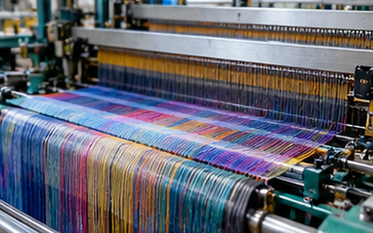
Start at the warp beam and follow the yarn towards the cloth. The beam releases warp into a guided path. The ends pass through the shedding arrangement and the reed, then become part of the fabric. The cloth leaves the forming area through the take-up arrangement and is collected.
The cloth fell is the boundary where new picks join the woven fabric. This location matters because beat-up acts there. A small shift between the reed and the fell can affect the next few picks. This can happen even when the weave program stays the same.
Motion | Main task | Evidence to examine |
|---|---|---|
Shedding | Place warp ends in the required opening | Correct end positions and a clear insertion path |
Insertion or picking | Deliver the required weft through the shed | Yarn arrival, condition and selection sequence |
Beat-up | Bring the inserted pick to the cloth fell | Reed motion, fell position and the formed cloth |
Let-off | Supply warp while controlling its tension | Warp delivery, beam state and tension over the cycle |
Take-up | Draw cloth away at the intended rate | Actual cloth advance and measured pick density |
Use this map to see how the functions connect. The five motions do not act as separate knobs. The exact drive, sensor and control arrangement depends on the machine. A motion may have its own motor and still depend on the other loom motions.
Moving cloth through a controlled take-up roll differs from winding it for storage. A growing collection roll changes diameter. The machine design must keep winding from disturbing the forming area. Find out which roll or encoder measures cloth movement. Check that basis before using its reading in a calculation.
Separate the weave instruction from the shed that forms
The weave plan says which warp ends should lie above or below a pick. The shedding mechanism must create the required opening at the right time. Correct pattern data are therefore only one part of correct shedding.
In frame weaving, heddles on the same shaft move together. Ends drawn into that shaft share its movement. A drawing-in error can cause a repeat fault in the fabric. The shaft may still follow its command exactly. Check the approved draft against the actual drawing-in and lift sequence. The controller may not be at fault.
CottonWorks' weaving guide explains frame control and the broad cam, dobby and Jacquard routes. They allow different forms of control. A dobby selects shaft movements, while a Jacquard harness can give much finer control of warp ends or groups. The installed harness determines the exact grouping.
The drive and the transmission must also suit each other. Stäubli's rotary-dobby description stresses a suitable match between the loom, the shedding system and its transmission. Its range does not imply that one shed height or timing suits every fabric.
An electronic drive must still move in time with the loom. For example, Stäubli's UNIVAL100 uses individual actuators and electronic coordination with the loom. That is a particular design. Other Jacquard machines may use different drives.
Check the opening where insertion actually occurs
A shed may look generous at one point while the yarn passage remains poor elsewhere. Check the intended path and the actual warp layers. Use the maker's approved procedure. Look for loose ends, uneven shaft positions and points that obstruct the yarn. These faults differ from a wrong weave repeat.
Do not judge the setting from height alone. The path must stay clear while the carrier or yarn passes through it. A static open-shed photograph cannot establish that timing. Use the specified phase reference and checking method for the machine.
The loom angle also needs a definition. Two screens may use different zero positions or directions. First check those references and the motion design. A number copied from another loom may use a different basis. Keep pattern selection, shaft travel and phase setting as separate entries in the setup record.
For a useful timing record, connect each event to both the machine phase and the pattern step. A shaft can be in the right position for one pick and the wrong position for the next. During repair, the pattern may have moved to a later step. A phase reading alone cannot then confirm the correct interlacement. Check the active step against the cloth boundary. This helps establish whether the next run will continue the same repeat. Use the maker's recovery procedure. Guessing which shaft should rise cannot establish the correct sequence.
See why a larger shed changes the yarn path
Opening the shed changes the length of the path that a warp end must follow. This is one reason that “open it more” can have effects beyond improving clearance.
Cloppenburg, Gloy and Gries studied warp-stop-motion positioning on an air-jet loom. Their 2015 paper connects the yarn-guide position, shed geometry and warp tension. It supports checking geometry when investigating tension. Its machine change is specific to that study, so it does not give a universal adjustment procedure.
A separate geometry example shows the connection. Imagine two fixed guide points at the same level. A heddle lies between them, 0.50 m from the rear point and 0.25 m from the front point. When the heddle is on that line, the straight path totals 0.75 m.
Now raise the heddle by h metres. Ignore guide thickness and let the yarn follow two straight segments. The required path becomes:
Path length = √(0.50² + h²) + √(0.25² + h²).
Heddle rise in this model | Total path | Extra path above 750 mm |
|---|---|---|
0 mm | 750.00 mm | 0.00 mm |
40 mm | 754.78 mm | 4.78 mm |
60 mm | 760.69 mm | 10.69 mm |
The extra path is about 0.64% of the original span at 40 mm rise. At 60 mm it is about 1.42%. The second rise is half as much again as the first. Yet the extra path has more than doubled in this example.
These percentages describe geometry. They are not measured yarn strain or a tension prediction. Let-off and other moving parts can supply extra yarn length. It can also stretch, slip or redistribute load. A force calculation would need those effects and the yarn's actual response.
The example points to three linked checks: clear passage, path length and tension. It does not establish an optimum shed height. Changing the front span, rear span or guide position changes the result. The same lift on another loom may need a different amount of extra path.
Understand what beat-up does and what it cannot prove
During beat-up, the reed brings the inserted weft towards the cloth fell. The reed also spaces the warp ends through its dents. These roles are related, but reed count is not pick density. Warp spacing across the width and weft spacing along the length are different measurements.
For a sound comparison, identify the reed, the drawing-in and the cloth construction. A changed reed can alter the warp path and available space. A take-up change can alter pick spacing while the number of reed dents stays the same. The final fabric must still be checked.
“Beat harder” is not a complete remedy for low pick density. First ask whether the actual cloth advance matches the intended number of picks. Also ask whether the fell, warp tension and insertion condition are stable. More force cannot supply a missing pick or correct a wrong measurement basis.
Keep motion and outcome separate in the record. A drive may reach the commanded position. The yarn can still respond differently if its material or tension has changed. An average cloth result may also look acceptable while a short section contains a fault.
The required evidence should connect the motion to the fabric made during it. Mark sample locations through the approved process and retain the relevant machine record. A loose swatch without its position cannot show which part of a trial produced it.
Link take-up to the number of picks
For a simple steady case, cloth advance and pick density are reciprocal. Let P be the number of inserted picks per metre of cloth at the stated measurement condition. The average advance per pick is:
Advance per pick = 1 ÷ P metres.
This relation assumes that the counted picks remain in the measured length. This does not mean that all take-up systems move in equal, separate steps. A continuous drive and an intermittent one can have the same average advance. Their movements within the cycle can still differ.
Suppose the target is 22 picks/cm, or 2,200 picks/m. The corresponding average cloth advance is:
1,000 ÷ 2,200 = 0.4545 mm per pick.
Over 4,800 retained picks, the target length is 4,800 ÷ 2,200 = 2.1818 m. Now suppose an independent measurement gives 2.2000 m at the same cloth state. The resulting average density is:
4,800 ÷ 2.2000 ÷ 100 = 21.82 picks/cm.
The measured length is about 18.18 mm greater than the target length, or 0.83% greater. The figures reveal a mismatch to investigate. They do not identify the failed part.
Check what the controller counts. Does it record shaft turns, insertion commands or confirmed retained picks? Pick finding, removal and repair can make those totals differ. Align the count interval with the two marked cloth boundaries. Otherwise, a correct division can combine two unrelated quantities.
For instance, suppose a separate log contains 1,004 successful one-pick insertions. Four of those picks were then withdrawn, with no other addition or removal. The marked section therefore retains 1,000 picks. If its measured length is 500 mm, its average density is 20 picks/cm. Using the gross insertion total would give 20.08 picks/cm. This count assumes that every insertion and withdrawal falls within the marked boundaries. If a repair record is unclear, keep it open for review. Do not silently count it as cloth output.
Then compare encoder movement with actual cloth movement. Check the cloth state, contact condition and the parts that grip it. Do not assume that a displayed roller length is automatically the relaxed fabric length.
Check which way a setting changes the movement. Increasing physical cloth advance per retained pick lowers the density. A screen field labelled “picks/cm” may command the reverse change in drive movement. Read the machine's definition of that field. A higher number does not always mean faster take-up.
Keep finishing changes out of the loom calculation
A pick density belongs to a stated fabric condition. It can change when the cloth changes length after weaving, even though no picks are added.
Consider a separate case with 10.00 m of cloth at 22 picks/cm. It contains 22,000 picks over that length. Suppose those same picks remain in 9.50 m after a defined finishing route. The density becomes 23.16 picks/cm.
The relation is finished density = earlier density ÷ retained-length fraction. Here the fraction is 0.95. If the required finished density were 24 picks/cm, the matching earlier density would be 24 × 0.95 = 22.8 picks/cm, under this same assumed length change.
This arithmetic helps explain the planning question. It does not validate a finishing allowance. It assumes that no picks are removed. The length change must also be known between clearly defined fabric states. Use trial evidence for the actual fabric. ApparelDiary's shrinkage testing guide explains why reference dimensions and treatment conditions matter.
ISO 7211-2:2024 covers methods for determining threads per unit length in woven fabrics. Its public scope identifies three methods. A formal result needs the complete method and the agreed fabric condition. A loom display does not perform that test.
Let off the required warp as the beam changes
Let-off supplies yarn to a system whose demand changes during weaving. Its task includes controlling tension as the beam becomes smaller. At a fixed rotation speed, the beam supplies less length as its radius falls.
The simple relation between surface speed and rotation is v = r × ω. Here v is linear speed, r is radius and ω is angular speed in radians per unit time. OpenStax explains this relationship. The following invented beam case applies that relation.
Suppose a separate example needs 0.24 m/min of warp delivery. With a beam radius of 0.40 m, the required speed is:
0.24 ÷ (2 × π × 0.40) = 0.0955 revolutions/min.
At 0.20 m radius, the same linear delivery requires 0.1910 revolutions/min. The beam speed doubles when the radius halves. These are beam speeds, not loom picks per minute or motor speeds before gearing.
The beam torque has a radius effect too. For a simple tangential warp pull F, its moment about the beam axis has magnitude F × r. The OpenStax torque explanation gives the force-and-lever-arm basis.
If the total tangential pull is an invented 1,800 N, the corresponding moment is 720 N·m at 0.40 m radius and 360 N·m at 0.20 m. Now hold the resisting torque at 720 N·m at the smaller radius. In this ideal balance, the pull would be 3,600 N.
This is not a motor-sizing calculation. It omits acceleration, friction, transmission losses and other loads. Yarn-path angles can also affect the force that the real tension sensor measures. Use the maker's calibration and drive model for the real machine.
Nor must warp delivery equal cloth advance metre for metre. Warp follows a curved path within woven fabric, and its state under tension matters. Compare actual consumption and cloth length on defined bases. A difference is not automatically evidence that one of the two drives is slipping.
Read tension as a signal over time
“Constant warp tension” usually describes a control aim. It does not prove that the force on every end stays the same throughout the weaving cycle. Shedding changes the path, and beat-up adds a changing demand at the forming area.
A slow display may show a useful average while missing short peaks. Before comparing readings, check the sensor position and units. Also check how it samples the signal and what statistic it displays. A reading for the whole warp sheet cannot show how evenly its load is shared among the ends.
For example, two records can each average 100 units while covering different ranges. A signal alternating equally between 90 and 110 has that mean. So does one alternating equally between 60 and 140. Their peak-to-peak ranges are 20 and 80 units. The second range is four times larger, although the averages agree.
Those invented units illustrate a measurement problem, not a suitable yarn tension. Real comparisons need a calibrated signal and an agreed phase reference. Check whether readings include running, stopping or restarting before pooling them into one mean.
Toyota's JAT910 brochure describes synchronized control of let-off, take-up and other devices. It also identifies start-up acceleration as part of its stop-mark control. This shows why the change from stopped to running needs a separate check. It does not guarantee a defect-free restart on every fabric.
Distinguish a yarn-fault stop from protection for people
Warp and weft detectors help limit faulty production. Their designs and the conditions they detect vary. A warp drop wire can indicate a broken end, while a weft detector monitors a specified part of insertion. A stop code identifies what the system sensed. It may not identify the original cause.
Groz-Beckert's drop-wire guidance relates selection to yarn properties, density and pattern. Use its product guidance to check the installed parts. It is not a reason to choose a heavier wire for every problem or bypass a troublesome detector.
These production functions do not replace guards, interlocks or isolation. UK HSE's weaving guidance addresses guarded drives, shedding and insertion, as well as safe access and isolation for repairs. This is UK guidance, not a statement of Bangladesh law. Follow the applicable local requirements and the machine's approved procedures.
Do not reach into a moving shed to inspect a motion. Use the prescribed safe checking mode and competent support. A stopped production cycle does not prove that the machine is safe to access. Hazardous movement or stored energy may still be present.
Investigate one discrepancy without losing the whole process
Choose the first check from the observed fault. A repeat-pattern error points towards the draft, drawing-in and lift sequence. A low average pick density calls for a count-and-length reconciliation. An insertion failure needs evidence about the yarn passage and arrival. These are starting points, not automatic diagnoses.
Keep a short record linking the observation to its cloth location. Include the fabric style, yarn lot, beam state and relevant setup. Preserve the original values before changing anything. Keep the question in view. Collect the details needed to explain the comparison, rather than every screen field.
If the machine shows correct shaft commands but the cloth repeat is wrong, check the actual end assignment. If density changes while the command stays fixed, compare cloth movement and measurement state. If a problem grows as the beam empties, include the changing radius and tension response in the investigation.
Make an approved change that addresses the identified question. Then examine the required fabric properties as well as the immediate symptom. A larger shed might clear the insertion path yet cause more end damage. That would not be an acceptable setup. A correct average density does not excuse a visible local band.
Use repeat observations under the relevant conditions before releasing the setting. ApparelDiary's quality assurance and quality control guide explains the connection between process control and release evidence. Keep the actual cloth result attached to the decision.
The aim is a setup whose motions work together. The intended ends form the shed, the right weft arrives, and the reed forms the cloth. Warp supply and cloth removal then maintain that process within its approved range. Understanding the motions together makes each setting easier to explain and each fault easier to investigate.



Discussion0
Loading the discussion…