
Control the water loss before buying heat recovery
Boiler blowdown protects water quality by removing some concentrated boiler water. That discharge also carries heat and treated water out of the steam system. A textile plant needs enough blowdown to meet its approved water programme. It can then recover useful heat from the flow that remains.
These are two separate projects. Better control may reduce an excessive discharge. Heat recovery may reuse energy in the required discharge. Estimate them in that order. Do not size recovery equipment around a wasteful flow. It may be too large once the control fault is fixed.
This guide develops a dissolved-solids balance and checks blowdown percentages. It then follows heat into a real receiving load. All numerical plant cases are hypothetical. Their water limits, prices, and service hours illustrate the method. They are not operating instructions for a real boiler.
Know which blowdown stream you are studying
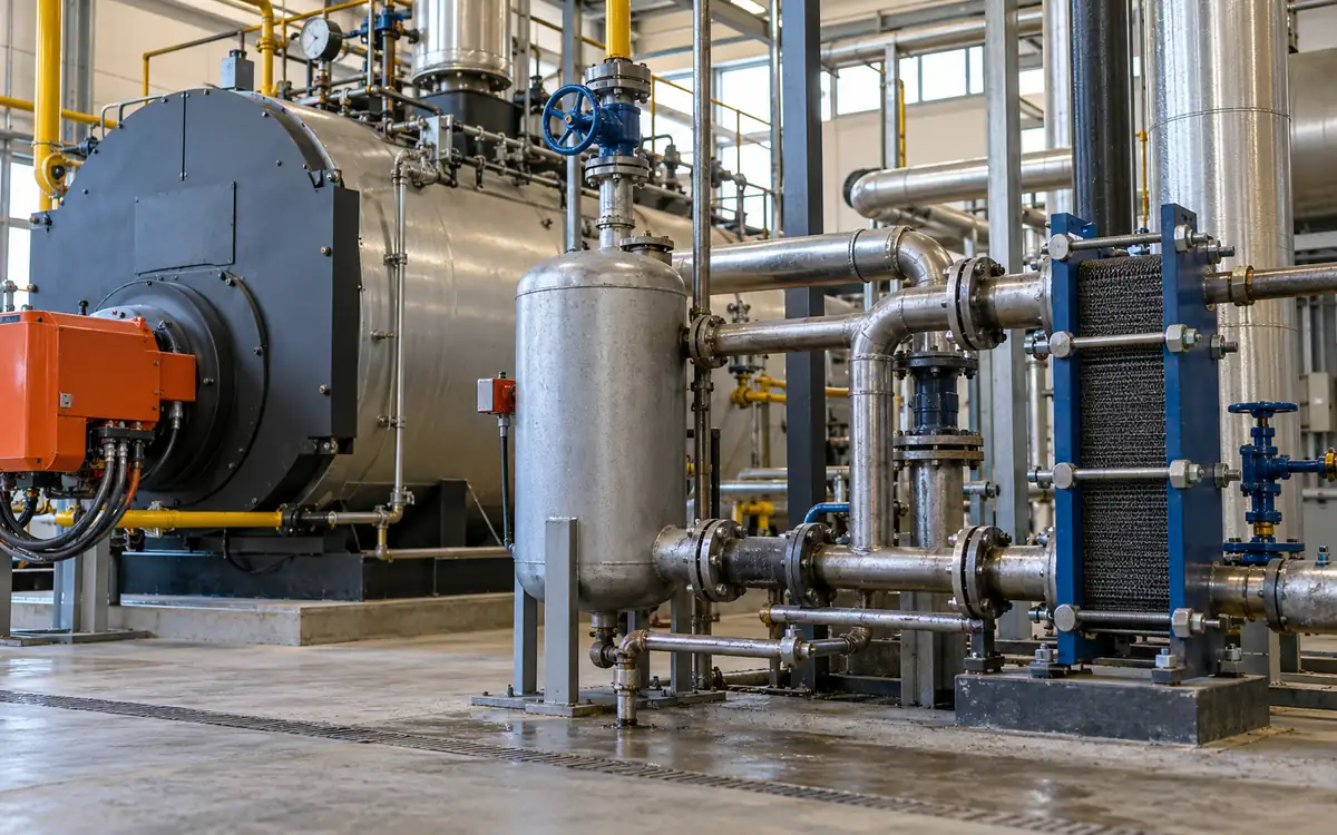
Surface or TDS blowdown controls dissolved material in boiler water. Bottom blowdown removes settled material. Their purpose, flow pattern and equipment differ. The DOE blowdown guide explains this distinction. It also weighs the risks of too little discharge against needless water loss.
Draw both routes on the survey sheet. Identify the boiler connection, control valve, downstream vessel and final discharge. Record how TDS flow is controlled. It may be continuous, switched by an automatic control, or manually operated. A valve position alone does not establish its annual mass flow.
Keep bottom-blowdown requirements within the approved operating procedure. Keep each required sludge-removal step. A heat-recovery cost estimate does not justify cutting it. Its short bursts also create a different design duty from a steadier TDS stream.
Check the scope of any proposed recovery package. For example, this Spirax Sarco manual covers a TDS blowdown system. It requires bottom blowdown to remain separate. That restriction belongs to the equipment design and must survive procurement and installation.
Establish the chemistry limit through the water programme
A plant should not choose a concentration limit from an energy spreadsheet. Obtain the limits set for the boiler, pressure, treatment scheme and steam use. Ask the water specialist which measured variable controls discharge. Check which other limits could be reached first.
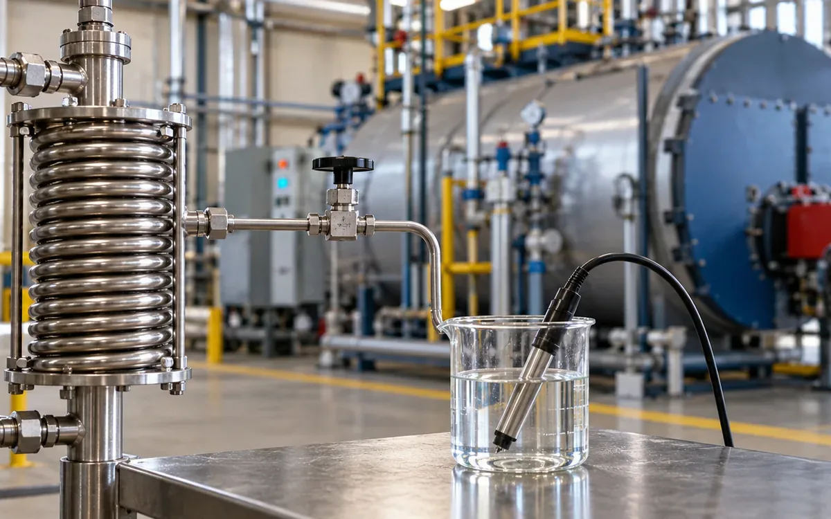
Conductivity is useful for control. It does not directly measure all solids in every type of water. Its relation to dissolved concentration depends on the water and the method used. Temperature also affects the reading. Keep the probe's compensation, calibration and sample method consistent with the treatment programme.
The Spirax Sarco guidance on TDS control explains representative sampling and sample cooling. Water taken near a feed inlet may not represent the boiler. Poor sampling can cause flashing. That changes sample concentration and can expose the operator to hot discharge.
Keep laboratory and field results for the audit. Add the date, sample point, temperature basis, and test method. A display marked “2,500” is incomplete evidence without units and context. It may represent conductivity, a calculated TDS value or a configured control signal.
Build a mass balance with clear symbols
Use mass flow for the calculation. This avoids mixing hot-water volumes with cold-water volumes without correcting density.
Symbol | Meaning | Example unit |
|---|---|---|
S | Steam leaving the boiler | kg/h |
B | Blowdown leaving the boiler | kg/h |
F | Feedwater entering the boiler | kg/h |
R | Condensate returned to the feed system | kg/h |
M | Fresh makeup entering the system | kg/h |
C | Concentration of the chosen dissolved constituent | mg/kg |
For steady conditions with no inventory change or other water losses:
F = S + B
M + R = F
Therefore, M = S + B − R.
Now state the solids assumptions. The simple balance treats the selected constituent as nonvolatile. It assumes negligible amounts in steam and return condensate. It ignores added treatment solids and precipitation. These are modelling assumptions. Real treatment chemistry may require a fuller balance or a suitable conservative marker.
Under those assumptions:
M × C_makeup = B × C_boiler.
Substituting the water balance gives:
B = (S − R) × C_makeup ÷ (C_boiler − C_makeup).
This expression shows why condensate return matters. Fresh makeup brings the assumed dissolved load. Clean returned condensate supplies water without bringing the same load. Do not treat all steam output as fresh makeup here. That would overstate required blowdown.
Work through a concentration example
Suppose a textile plant has the following steady conditions. The concentration limit is hypothetical. Assume it has been accepted for this example's chemistry.
Input | Assumed value |
|---|---|
Steam production, S | 5,000 kg/h |
Clean condensate return, R | 3,000 kg/h |
Makeup concentration | 200 mg/kg |
Selected boiler concentration | 3,000 mg/kg |
The required model flow is:
B = (5,000 − 3,000) × 200 ÷ (3,000 − 200)
B = 142.86 kg/h.
Feedwater is 5,142.86 kg/h. Fresh makeup is 2,142.86 kg/h. Check the dissolved balance: 2,142.86 × 200 and 142.86 × 3,000 both give about 428,571 mg/h, allowing for rounding.
The value is a mass-balance result, not proof that this flow is safe for an actual boiler. Treatment additions, dirty condensate, or carryover would alter the result. Changes in stored water and sample error also matter. Review any mismatch between the model and measured operation before changing settings.
In a batch dyehouse, steam use and return can vary within the shift. Use a suitable averaging period or time-resolved balance. Do not combine a quiet-hour return reading with a peak steam rate. That pairing creates a condition that never existed.
Avoid the two common concentration-ratio mistakes
The ratio of boiler concentration to makeup concentration in the example is 3,000 ÷ 200 = 15. That is different from the ratio to mixed feedwater concentration.
Mixed feedwater receives the same dissolved load over 5,142.86 kg/h. Its calculated concentration is 83.33 mg/kg. The boiler-to-feedwater ratio is therefore 36.
Using this second ratio, the boiler-only balance gives:
B = S ÷ (36 − 1) = 142.86 kg/h.
Both routes agree because their boundaries agree. Inserting the makeup ratio of 15 into the boiler-only formula would give 357.14 kg/h. That result gives all feedwater the makeup concentration. The actual mixed feedwater has a lower value in this example.
Always label what “cycles” compares. A report should state boiler-to-makeup or boiler-to-feedwater and identify the measured constituent. A ratio may use conductivity. Check that the approved chemistry method allows this. A concentration label cannot repair a mixed boundary.
State the denominator in every blowdown percentage
For the same example, blowdown as a share of feedwater is:
100 × 142.86 ÷ 5,142.86 = 2.78%.
Blowdown relative to steam production is:
100 × 142.86 ÷ 5,000 = 2.86%.
The two percentages describe the same flow. They are not conflicting measurements. Check the target and log use the same base. A feedwater target cannot be directly compared with a steam-based percentage.
If b is the fraction of feedwater discharged, then B = S × b ÷ (1 − b). If r is blowdown divided by steam, then B = S × r. Write those definitions beside spreadsheet inputs and charts.
Use measured totals over the same period when assessing a running plant. Hourly steam rates and daily makeup totals have different time bases. A weekly blowdown estimate has another. Convert them to a matching operating period before combining them.
Estimate the benefit of correcting excess discharge
Assume the plant currently discharges 220 kg/h and can meet all approved limits at the modelled 142.86 kg/h. The avoided discharge is 77.14 kg/h. At 5,000 operating hours per year, it avoids about 385.7 tonnes of replacement water.
Use enthalpy to assess heat. The NIST water and steam tables provide a recognised property basis. For this hypothetical case, use boiler-liquid enthalpy of 762 kJ/kg. Use 104.8 kJ/kg for replacement makeup. These are stated inputs. A real calculation must use actual pressure and temperature.
Avoided useful heat per year is:
77.14 × (762 − 104.8) × 5,000 ÷ 1,000,000 = 253.5 GJ.
At an assumed marginal boiler efficiency of 0.82, avoided fuel energy is 253.5 ÷ 0.82 = 309.1 GJ. At 9 currency units per GJ, the annual fuel benefit is about 2,782 currency units.
Assume replacement water and its treatment cost 1.50 currency units per tonne. The water benefit is about 579 currency units per year. After an added annual control-service cost of 300, net benefit is about 3,061. A complete installed control cost of 5,000 would give a simple payback near 1.63 years.
This case assumes no existing recovery of the heat in the avoided discharge. If recovery already exists, less heat may be lost when blowdown falls. Recalculate the whole affected balance. Do not add the full reduction benefit while keeping recovery savings unchanged.
Assess recovery against the remaining flow
After better control, about 142.86 kg/h remains for recovery in this example. Its gross heat difference above incoming makeup is:
142.86 × (762 − 104.8) ÷ 3,600 = 26.08 kW.
That is a boundary limit, not a guaranteed exchanger duty. Some heat must remain in the discharge. Heat transfer needs a temperature difference. Pipe losses and stops may reduce useful recovery. A lack of cold makeup can also limit it.
The DOE blowdown-recovery guide describes heat exchangers and flash recovery. A useful appraisal follows the energy to the water or other load that receives it. A hot outlet pipe is not evidence of avoided boiler fuel on its own.
Assume the design delivers an average 20 kW of useful heat. It operates for the same 5,000 hours. The annual useful heat is 360 GJ. At efficiency 0.82, this displaces 439.0 GJ of fuel, worth about 3,951 currency units.
If an added pump uses 0.25 kW at 0.12 currency units per kWh, electricity costs 150 per year. Allow a further 400 for service. Net annual benefit is about 3,401. A 12,000 installed cost gives a simple payback near 3.53 years. These inputs must be checked against quotations and measured duty.
Count flash steam and liquid heat once each
When hot blowdown enters a lower-pressure vessel, part may flash into steam. A simplified adiabatic flash fraction is:
x = (h_in − h_f) ÷ h_fg.
Here h_in is incoming liquid enthalpy. At the receiving pressure, h_f is saturated-liquid enthalpy and h_fg is latent heat. Use a common property basis. The Spirax Sarco recovery guide explains the two streams. Separated vapour and liquid can serve different heat-recovery stages.
For an illustrative atmospheric flash step, use h_in = 762, h_f = 419 and h_fg = 2,257 kJ/kg. The fraction is about 0.152. Of 142.86 kg/h entering, about 21.71 kg/h becomes vapour and 121.15 kg/h remains liquid.
Assume the vapour condenses at that receiving condition. Its latent heat supplies about 13.61 kW. If the remaining liquid cools from 100°C to 50°C, using heat capacity 4.18 kJ/kg·K, its contribution is about 7.03 kW. The combined idealised duty is 20.64 kW.
Do not apply liquid cooling to the original 142.86 kg/h after already allocating 21.71 kg/h to flash steam. Also do not add the full incoming enthalpy to these two duties. They are parts of the same incoming energy, not new energy created by flashing.
Confirm that the receiving system can use the heat
Plot makeup demand and blowdown availability on the same time base. A heat exchanger needs both streams. A hot-water tank may help bridge a mismatch, but it adds capacity limits, losses and control needs.
Check the proposed receiving temperature against the feed system's design. Do not heat the tank beyond its useful range. This can create other problems, such as poor pump suction conditions. Check the whole boiler-house system. The exchanger rating alone is not enough.
Record where saved steam appears in the balance. If recovered heat replaces steam used to warm a feedtank, show that avoided steam duty. Another recovery source may already keep the tank at its target. Added blowdown heat may then replace that source, with no fuel saving.
Keep the water streams distinct. An approved exchanger transfers heat. It does not make dirty residual blowdown suitable as makeup water. Assess condensed flash water separately if it will be recovered. Check both its quality and the equipment needed.
For the wider service boundary, use the plant's utility load register. Record the added pump, controls, and heat destination. The recovery package does not add production capacity.
Design control and maintenance into the proposal
Ask the designer to state rated pressures, temperatures, materials and allowable flows. Review the flash vessel and relief arrangements. Check drainage, expansion, access, and the discharge route as parts of one system. Equipment selection and pressure-system changes need competent engineering review.
Make fouling access part of the purchase decision. The dirty side of the exchanger may need inspection or cleaning. A low price may conceal high service costs. Long shutdowns for maintenance can reduce the benefit over the equipment life.
Specify how the system behaves when the receiving water is too hot, makeup flow stops or a pump fails. Recovery failure must not prevent the boiler from carrying out required blowdown. The approved design should provide the necessary safe operating response.
Agree the evidence required at handover. Include sensor IDs and calibration records. Add commissioning results, control settings, manuals, and a marked drawing. Place continuing tasks in the maintenance programme with named ownership.
Diagnose poor results without weakening water control
Observation | Questions to resolve |
|---|---|
High discharge despite low indicated concentration | Is the probe representative and calibrated? Does the valve close correctly? |
Rising concentration with little discharge | Is the sample sound? Is flow restricted? Does the control signal reach the valve? |
Hot residual discharge after recovery | Is cold-side flow present? Is the exchanger fouled? Has inlet temperature changed? |
Less fuel benefit than forecast | Are useful hours lower? Is another heat source displaced? Was the original loss overstated? |
Unstable readings after process changes | Did return quality, makeup quality, treatment dose or boiler load change? |
Use trends and physical checks to test each explanation. Avoid changing several settings at once just to make a chart look better. Lower discharge has no value if water quality falls outside its accepted range. Check steam purity too.
When a meter is unavailable, label the flow estimate and its uncertainty. Valve duty cycle alone does not measure mass flow. First validate how flow relates to the duty cycle. Pressure changes and valve condition can make a fixed litres-per-minute assumption unreliable.
Test the estimate against changes in return and operating time
The steady example is a starting point. Build the annual case around conditions the mill actually expects. Keep the approved concentration limit fixed while changing the water inputs. This shows which assumptions drive cost and savings. The chemistry requirement stays fixed.
For example, retain steam production of 5,000 kg/h and makeup concentration of 200 mg/kg. If clean return falls to 2,500 kg/h, the simple model requires 178.57 kg/h of blowdown. If return rises to 3,500 kg/h, it requires 107.14 kg/h. Both values come from the same formula and the same hypothetical 3,000 mg/kg boiler limit.
More return can therefore reduce the flow available for heat recovery. The overall water system improves. That remains true even if the recovery unit supplies less heat. Do not judge the unit only by annual recovered heat. That could reward needless blowdown. Pair its performance with the amount of necessary blowdown it receives.
Operating time matters just as much. If the recovery example delivers 20 kW for 3,000 hours instead of 5,000, useful heat falls to 216 GJ. At the same efficiency and price, gross fuel benefit falls to about 2,371 currency units. Pump cost falls to 90, but an assumed fixed service cost of 400 remains. Net benefit is then about 1,881, and the 12,000 investment takes about 6.38 years to repay simply.
Do not use a single average when the source and receiver have different schedules. Build a table for each hour or batch period. Include available blowdown, cold-side demand, and useful duty. Sum the useful heat from those periods. Check the source, receiving load, and exchanger limits. The lowest controls the result for that period.
Separate a screening estimate from an investment decision
An early estimate helps decide whether to measure further. An investment case needs a tighter definition of installed cost and continuing work. Include access, foundations or supports, piping, and instruments. Add electrical work, commissioning, and planned production stops. Show taxes or financing only if they belong to the site's comparison method.
Ask the supplier which performance is guaranteed and under what inlet conditions. A rated duty at full cold-water flow does not establish annual useful recovery. Request a calculation for the expected range. Include lower blowdown after the control work. Also test warmer makeup water in the hot season.
Use low, central and high estimates for uncertain hours and heat delivery. Keep water-treatment limits fixed in this exercise. Use other operating cases only if the responsible specialist approves them. The cost model should describe a valid design. It should not encourage staff to exceed agreed operating limits.
Verify savings and keep the two projects separate
For control improvement, compare blowdown, steam, makeup and return over matched periods. Retain chemistry evidence showing that the lower discharge still meets the agreed programme. Explain changes in product mix or direct steam use that alter makeup demand.
Measure receiving flow and temperature rise to calculate useful heat. Use suitable density and heat-capacity values. Cross-check the hot side when practical. Large unexplained differences may indicate timing, measurement or boundary errors.
Keep two benefit lines. One is avoided needless discharge. The other is useful heat from required discharge. This keeps a later improvement in condensate return from being counted twice. Return changes may lower both makeup need and the heat available to the recovery package.
Update the site's overall heat balance. Link the result to its boiler capacity and steam-demand balance. Keep this project's claim tied to the measured losses it changes.
Frequently asked questions
Is zero blowdown the right energy target?
No. The required flow follows the approved water programme and actual contamination load. The useful target is reliable chemistry control with no needless discharge. A lower number alone is not evidence of better operation.
Can conductivity be converted to TDS with one fixed factor?
Only use a conversion accepted for the actual water and test method. Different dissolved materials and temperature conditions affect the relationship. Keep calibration and sample records. These let the team compare the controller with independent checks.
Should heat recovery be sized before the control upgrade?
Establish the expected controlled flow first. Then size recovery for its real range and receiving load. Current over-discharge may create an attractive paper saving. That saving can disappear once the operating fault is fixed.
Does lower drain temperature prove the whole saving?
It shows less heat leaving in that stream under comparable conditions. Fuel savings need a useful receiving duty and enough operating time. Identify the heat source being replaced too. Verify both sides of the energy story.
Make the business case follow the water balance
Start with the chemistry and identify the correct blowdown stream. State the basis of every concentration and percentage. Reduce avoidable flow first. Assess heat recovery from what remains. Check that the receiving system can use that heat.
Keep matched measurements and calculations that others can repeat. Add the maintenance needs and a clear verification plan. This evidence supports the claimed savings. It also protects water control and prevents counting the same heat twice.
References
DOE: Minimize Boiler Blowdown.
DOE: Recover Heat from Boiler Blowdown.
Spirax Sarco: Controlling TDS in Boiler Water.
Spirax Sarco: Heat Recovery from TDS Blowdown.
Spirax Sarco: Blowdown Heat Recovery Installation and Maintenance.
Discussion0
Loading the discussion…