
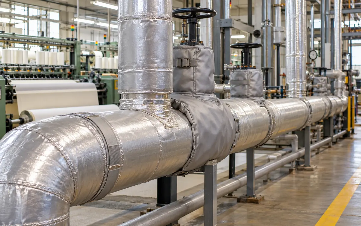
Treat insulation as a maintained part of the steam system
A missing section of steam-pipe insulation is easy to see and easy to postpone. The pipe still carries steam, so production may continue without an obvious alarm. Yet the bare surface loses heat for every hour it remains hot. The repair also affects access and surface temperature. It can affect the pipe beneath it for years.
An effective insulation programme does more than count bare metres. It records the actual pipe size, temperature, operating schedule, exposure and condition. It compares repair options. It also assigns someone to replace insulation after maintenance.
The DOE guide to steam-line insulation points to three common problems. Insulation may be missing, damaged, or wet. Its heat-loss tables state their test assumptions. These include air temperature, wind, and annual hours. Those conditions must be checked before applying the figures to a textile mill.
This article explains how to move from a field survey to a defensible repair list. The worked examples are hypothetical and illustrate the calculation method. They are not material specifications or predicted savings for a particular factory.
Set the repair objective before choosing thickness
Set a clear goal. It may be lower fuel use or a cooler outer surface. It may be steadier process conditions or less heat lost from a return stream. More than one objective can apply to the same pipe.
State the required result in the job brief. “Insulate the pipe” leaves too much open. State the service temperature and local conditions. Define the material, access needs, and evidence needed to accept the work. List valves and fittings that staff must reach to operate or inspect.
Do not use one thickness for every line simply because it is easy to buy. A main may stay hot all day. An outdoor return or short-use press branch has a different duty. Their economic rankings can differ even when the pipe diameters match.
A calculated outer temperature is also not a universal touch-safe limit. Contact time, surface material, access and the applicable safety assessment matter. Ask the responsible engineer to set the protection requirement. Use the calculation to check the proposed design against it.
Survey sections with consistent boundaries
Divide the route into sections with similar duties. Group pipes by size, temperature, local conditions, and service hours. Give each section an ID linked to a drawing or a clear location. Count fittings separately so they do not disappear inside a straight-pipe allowance.
Measure the actual outside diameter where practical and safe. Nominal pipe size is a label. It may differ from the outside diameter needed for the heat-loss equation. Record the current insulation thickness and outer cover. Do this only where it can be checked without disturbing the system.
Survey item | Record | Decision it supports |
|---|---|---|
Geometry | Outside diameter, length and fitting count | Heat-loss area and quantity estimate |
Duty | Hot temperature, hours and shutdown pattern | Annual energy calculation |
Environment | Indoor, outdoor, air movement and washdown | Heat transfer and weather protection |
Condition | Missing, wet, crushed, loose or damaged | Repair scope and underlying cause |
Access | Height, congestion and removable parts | Installed cost and work planning |
Integrity concern | Corrosion signs, leaks or damaged support | Inspection before covering |
Separate confirmed dimensions from estimates. An inaccessible line can remain in the register with a survey action. A guessed diameter can give the wrong quantity and heat loss. The budget may look precise but still be wrong.
Find why the insulation failed
Missing insulation often follows a valve repair. Wet insulation may follow a pipe leak, damaged jacket or repeated washdown. Crushed material may reveal that people use a pipe as a step. Replacing the insulation without addressing the cause can recreate the same defect.
Trace water entry and examine how the jacket sheds water. Check penetrations, overlaps and terminations. Have the appropriate team inspect suspect pipework before it is covered again. A new outer finish can hide a continuing integrity problem.
The HSE corrosion guide explains a risk from poor installation. Insulation can hold moisture against equipment and promote external corrosion. Choose a suitable coating and weather protection for the service. Add a clear inspection plan.
The survey should not require untrained workers to remove unknown old insulation. Identify the material and apply the site's controls before disturbance. Record unresolved concerns about the material or pipe condition. Put them in the job scope so the price covers the required work.
Understand the three parts of heat loss
Heat travels through the insulation by conduction. It then leaves the outer surface by convection to the air and by radiation to the surroundings. Increasing thickness changes the conduction path and the outer area. Surface finish and air movement affect the losses from that outer area.
The NIA design data gives the relevant equations. They cover heat flow through cylinders and from outer surfaces. Thermal conductivity varies with temperature. The surface coefficient also changes with the conditions of each installation.
This is why a single percentage reduction should remain a screening assumption. Two pipes can carry steam at the same pressure yet lose different amounts of heat. One may be outdoors in moving air. The other may be sheltered. Wet or crushed material may behave differently too. Dry product data may not describe its performance.
Use material data at a suitable mean temperature. Model the actual surface and its surroundings. Keep those inputs in the report. Another engineer should be able to rebuild the result. An unexplained software total is hard to check.
Use a simple cylindrical calculation carefully
Consider a long pipe with uniform insulation and a steady temperature. A simple model adds two thermal resistances per metre:
R′ = ln(r₂/r₁) ÷ (2πk) + 1 ÷ (2πr₂h).
Heat loss per metre, q′ = (Tₕ − Tₐ) ÷ R′.
Here, r₁ is the pipe's outside radius and r₂ is the insulation's outside radius, both in metres. The assumed insulation conductivity k is in W/(m·K). The combined outer-surface coefficient h is in W/(m²·K). Tₕ and Tₐ are the hot boundary and ambient temperatures.
The resistance R′ has units of m·K/W, giving q′ in W/m. This version neglects pipe-wall and inside-film resistance. It assumes the chosen h covers both convection and radiation. Use it to understand the effect of thickness. A full design needs more detail.
ISO 12241:2022 gives calculation rules for industrial insulation. It mainly covers steady conditions and also addresses thermal bridges. Supports and fittings may need their own calculations. Changing operating states may also need more than a simple straight-pipe model.
Compare two thicknesses in an original example
Assume a hypothetical pipe has an outside diameter of 89 mm, so r₁ is 0.0445 m. The hot boundary is 160°C and ambient air is 30°C. Use a constant conductivity of 0.05 W/(m·K) and a combined surface coefficient of 10 W/(m²·K).
These are declared teaching inputs. A real design would obtain temperature-dependent material data and calculate suitable surface coefficients. Here they stay fixed. This shows how the geometry changes the result.
For bare pipe under the same simplified surface assumption:
q′bare = h × 2πr₁ × (160 − 30) = 363.5 W/m.
With 25 mm of insulation, r₂ is 0.0695 m. Substituting in the resistance equation gives a heat loss of about 78.9 W/m. With 50 mm, r₂ is 0.0945 m and heat loss is about 50.7 W/m.
Option | Calculated heat loss | Reduction from bare pipe | Calculated outer temperature |
|---|---|---|---|
Bare pipe | 363.5 W/m | — | 160.0°C hot boundary |
25 mm insulation | 78.9 W/m | 284.6 W/m | 48.1°C |
50 mm insulation | 50.7 W/m | 312.8 W/m | 38.5°C |
The outer temperatures follow from Tₐ + q′/(2πr₂h). These are model outputs. They are not field readings or safety approvals. The thicker option saves more heat. The extra saving is smaller than the benefit from the first layer.
Convert avoided heat into fuel cost
Now assume the example covers 85 metres and remains hot for 5,000 hours a year. Ignore fittings and supports in this first calculation. For 25 mm insulation, the avoided thermal power is:
(363.482 − 78.877) W/m × 85 m ÷ 1,000 = 24.191 kW.
Annual avoided heat is:
24.191 kW × 5,000 h × 0.0036 = 435.45 GJ.
Assume the marginal boiler efficiency is 80%, on the same fuel heating-value basis used in the cost. Avoided fuel energy is 435.45 ÷ 0.80 = 544.31 GJ. At 9 currency units per GJ, the annual fuel saving is about 4,898.78 currency units.
Use the actual hours that the pipe is hot. A branch supplied through nights and weekends can lose heat outside production hours. Another branch may cool soon after its last batch. A calendar based only on sewing shifts will not describe both correctly.
The boiler's response also matters. Choose an efficiency that reflects the heat displaced. A full-load catalogue figure may not describe the actual boiler duty. Link the project to the steam-demand and boiler-capacity record. Keep its heat-loss calculation separate and clear.
Compare the extra thickness on its extra benefit
Suppose the installed cost is 4,200 currency units for the 25 mm option and 6,500 for the 50 mm option. The thicker option saves about 5,384.29 per year under the same assumptions.
Decision measure | 25 mm | 50 mm |
|---|---|---|
Annual avoided heat | 435.45 GJ | 478.60 GJ |
Annual avoided fuel | 544.31 GJ | 598.25 GJ |
Annual fuel saving | 4,898.78 | 5,384.29 |
Installed cost | 4,200.00 | 6,500.00 |
Simple payback from bare pipe | 0.86 years | 1.21 years |
The extra 25 mm costs 2,300 and saves an extra 485.51 a year. Its incremental simple payback is therefore about 4.74 years. Use this comparison to decide whether the extra thickness is worthwhile.
It does not automatically decide the specification. The thicker option may be needed to meet a surface-temperature limit. A longer service life may also justify its extra cost. Conversely, the pipe may be scheduled for removal before the extra cost is recovered. Use the required service period and the site's investment method for the final choice.
Check the uncertainty before ranking the work
Hours, surface conditions, material conductivity and installed access cost can change the ranking. Test ranges that are plausible for the actual section. Find which inputs matter most. Do not add the same percentage allowance to all of them.
For the 25 mm example, reducing hot hours from 5,000 to 3,000 lowers annual fuel savings from about 4,899 to 2,939. The installed cost remains 4,200, so simple payback increases to about 1.43 years. The shorter duty causes that change. The insulation still performs as designed.
Outdoor wind may alter heat transfer. Wet insulation can change material performance. Those changes need a revised thermal model. They cannot be represented reliably by changing only the operating hours.
Show a central estimate and the main decision-sensitive range. If the preferred option changes within that range, collect better data before purchase. If the choice remains sound, record the uncertainty. Use a suitable specification and proceed. Perfect precision may not be possible.
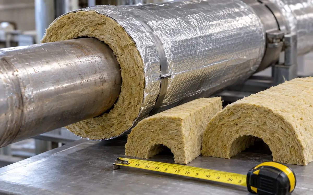
Include valves, flanges and removable jackets
Fittings can create gaps in an otherwise well-insulated route. Their shapes, access needs and repeated maintenance make them different from straight pipe. Give each fitting an ID. Use a calculation or supplier assessment that fits its actual shape.
The DOE removable-cover guide describes reusable insulation. It covers valves and other irregular shapes. These covers save heat and aid maintenance. Staff can remove and refit them. They are then less likely to be discarded after routine work.
Specify the fitting ID on each jacket and provide a clear refitting method. Check access to valve operation, indicators and inspection points. Staff may remove a jacket that blocks normal work. The estimated annual benefit would then be unrealistic.
Steam traps require particular care. Follow the trap maker's insulation instructions. Some trap types depend on heat exchange with their surroundings. Do not assume every hot part needs the same wrap. Check how each part works.
Use software as a documented calculation
Software can use conductivity that varies with temperature. It can also handle radiation and standard shapes in more detail. NAIMA's 3E Plus guide describes a tool based on ASTM C680. It supports material data for insulation comparisons.
Keep the input file or a readable report with the project. Record geometry, service temperature, and local air conditions. Add surface finish, material data, service hours, fuel cost, and efficiency. State the software version and the date of the material data.
Review a small number of representative runs by hand. The purpose is to catch units, radius-versus-diameter errors and implausible assumptions. A result may be ten times larger than expected. Check for metres entered as millimetres. Also check W/m versus total watts.
Do not describe a software result as a measurement. It is a prediction based on inputs. Check the system when it enters service. Inspect it later to confirm that its condition still matches the design.
Interpret a thermal image with the surface in mind
A thermal camera can locate abnormal areas. A bright or dark patch does not directly measure insulation quality. The camera sees radiation from the surface, including reflected radiation. Shiny metal jackets can give misleading apparent temperatures.
Compare similar surfaces under similar conditions and preserve the camera settings. Record the pipe duty, ambient conditions and any direct sunlight or strong reflection. An image taken just after startup may show a different pattern. Compare it with a stable hot line.
FLIR's measurement guide lists the inputs to check. They include emissivity, reflected temperature, distance, and window compensation. A low-emissivity surface reflects its surroundings. This can make it appear warmer or colder than it is.
Use thermal evidence to guide inspection. Check the installed repair under controlled conditions. Do not convert a surface colour into an annual fuel-saving claim. The energy estimate still needs dimensions, material properties, and operating conditions. State the calculation method too.
Make the quotation cover the complete installed system
A supply-only price can make insulation look cheaper than it is. Include access equipment and preparation. Add removal, disposal, pipe inspection, and suitable coating. Price the insulation, outer protection, and full reinstatement. Identify any shutdown or work-permit needs.
Ask bidders to state their material, thickness, temperature range and outer-jacket construction. Confirm compatibility with washdown, chemicals, outdoor exposure and nearby equipment. Ask for a clear list of exclusions. Compare quotes using the same scope.
The NIA installation guide stresses dry material and a ready work area. It also calls for work to be planned with other trades. A detailed calculation cannot make up for poor installation. Check for wet stock, poor fit, and damaged outer protection.
For a phased programme, define the sections included in each phase. Shared access costs can make it economical to repair several nearby sections together. Show that saving in the installation budget. Grouping the work does not add thermal benefit.
Rank the backlog by consequence and achievable benefit
Begin with immediate integrity and access concerns through the site's normal maintenance process. Then rank the energy repairs. Consider annual loss, installed cost, service life, and how well the repair will last.
A long bare line is not always the best first job. A shorter line used continuously may save more per year. A small valve jacket may be cheap to install. An overhead main may need costly access equipment. A wet section may require leak correction before insulation work can be effective.
Keep technical necessity and financial priority visible as separate fields. This prevents a short payback threshold from delaying a required protective repair. It also keeps ordinary energy investments open to cost review. Do not assign a safety label without a basis.
Connect the backlog to the site's maintenance programme. Give every approved item an owner, planned date and verification method. A survey without funded and scheduled repairs will not change the plant's heat loss.
Verify the repair and preserve its value
Check installed thickness, coverage, material identification and outer protection against the approved scope. Inspect fitting covers and penetrations. Record any section left incomplete, with a reason and a date for closure.
Once the line returns to normal service, check for unexpected hot areas. Look for signs of moisture entry too. Compare the result with the design under known operating conditions. A support may have a gap. A jacket may be refitted poorly. Either can weaken an otherwise good installation.
Update the asset record with the repair date and materials. Add insulation reinstatement to work orders that require removal. Keep the valve repair open until its cover is back in place. A cover on a workshop shelf does not save heat.
Track recurring damage by location. If the same jacket fails each washdown cycle, review the construction and exposure. If people repeatedly remove a cover for access, improve the access arrangement. Maintenance should address the cause so that the predicted savings persist.
Keep dimensions and quantities traceable through handover
The survey, quotation and completion record should use the same section identifiers. Otherwise, a measured length may become a quoted area. The invoice can then contain a quantity that nobody can reconcile. Keep the original diameter, length, and fitting count. Add the agreed unit used for pricing.
For the example above, 85 metres means 85 metres of straight pipe included in the thermal model. It does not mean 85 square metres of jacket. With 25 mm insulation, the ideal outer cylindrical area is 2 × π × 0.0695 × 85, or about 37.1 square metres. That area excludes overlaps, cuts, fittings and waste. A contractor's material allowance can exceed it without changing the heat-loss boundary.
Record such allowances openly. Do not increase the measured hot-pipe length to make the material order fit. That would inflate both the installed quantity and the predicted energy saving. Use separate lines for straight coverage, fitting covers and material allowances.
At handover, photograph the completed section and record exceptions against its identifier. Keep inspection access and equipment labels usable. Check the supports and moving connections. Confirm that their details match the approved design. These records help the next maintenance team restore the same construction. Staff should not have to guess its thickness or purpose.
Common questions about steam-pipe insulation
Is the thickest insulation always the best choice?
No. For normal steam pipes, extra thickness generally cuts heat loss. It adds cost and needs more space. Compare incremental benefit, service life and required surface conditions. Use an engineered specification for the final installation.
Can a generic heat-loss table support a budget?
Yes, if its assumptions fit the job. Check pipe size, temperature, surroundings, and service hours. State differences and use a suitable calculation for important decisions. A table may assume continuous service. It will overstate annual loss on a branch used only part-time.
Should wet insulation simply be covered with a new jacket?
First find how much material is wet and why. Inspect the equipment underneath as required. A new cover does not restore damaged material or remove trapped moisture. Follow the approved repair and material instructions.
Can fuel-meter data prove one small insulation repair?
Usually the plant has many larger changes affecting fuel use. Use the documented thermal estimate and installation evidence for the individual repair. A wider study can assess the combined programme. Do not assign every bill change to one pipe section.
Build a repair programme that lasts beyond the survey
Useful insulation work combines a credible thermal estimate with a durable installation. Measure the route and understand its duty. Fix the cause of damage. Compare suitable options on their actual costs and benefits.
Record what was insulated and why that design was chosen. Explain how the work was checked. Keep removal and reinstatement linked to maintenance work. The survey can then lead to lasting repairs and lower steam-system losses.
References
DOE: Insulate Steam Distribution and Condensate Return Lines.
NIA: Mechanical Insulation Design Data.
ISO 12241:2022: Industrial Insulation Calculation Rules.
DOE: Install Removable Insulation on Valves and Fittings.
NAIMA: 3E Plus Insulation Calculation Tool.
HSE: Corrosion and Selection of Materials.
Discussion0
Loading the discussion…