
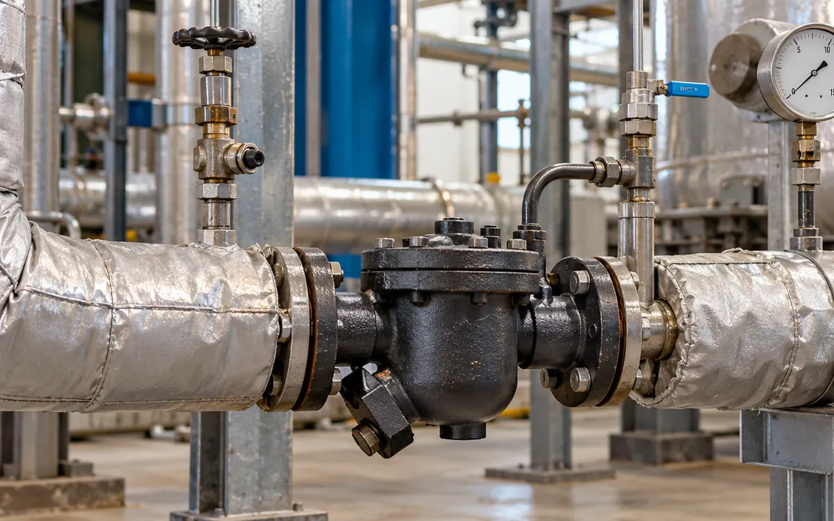
What a useful steam trap survey must prove
A steam trap survey should answer three questions. Is condensate leaving the equipment as it should? Is live steam escaping through a fault? Did the repair restore the required service? A list of hot and cold traps cannot answer all three.
In a textile mill, trap duty changes through a batch. A dyeing vessel may need rapid drainage while heating. It may need much less during a hold, and none after isolation. A trap tested at the wrong time may look blocked when the machine is simply idle. A continuously draining trap may also be healthy. Its type and current load matter.
Record the process state beside the instrument reading. This guide shows how to build that record and judge uncertain results. It also explains how to price losses and check repairs. It covers installed traps and their drainage duty. For a new boiler or added production load, use the separate guide to peak steam demand and boiler capacity.
The U.S. Department of Energy calls for regular trap checks and repairs. Its steam trap guidance treats sound, temperature and other tests as tools for finding faults. The useful factory result is a closed repair record supported by evidence.
Separate trap failure from a drainage problem
A steam trap drains condensate while limiting live steam loss. Some designs also let air leave the system. Its performance depends on more than its internal valve. Drainage depends on inlet and return pressure. The pipework, strainer, and process load also affect it.
Use two questions during diagnosis. First, does the trap mechanism work as intended? Second, can the whole installation pass the condensate load under the present conditions? A sound trap can sit in a system that cannot drain.
Consider a heat exchanger with a modulating steam valve. At light load, its steam pressure may be low. If the pressure behind the trap is greater, condensate cannot leave by pressure difference alone. Replacing the trap with an identical unit will not correct that condition. TLV's testing guide makes this distinction clear. A trap may be blocked, too small, or short of driving pressure.
Keep the report wording precise. Use wording that matches the evidence. For example, write “drainage failed during the hold stage; cause unconfirmed.” Do not convert every cold reading into “failed closed.” That shortcut sends the repair team towards the wrong job and makes the next survey less trustworthy.
Build a trap register that survives personnel changes
Give each installed trap a stable ID. A location such as “behind dyeing machine” is too vague once the layout changes. Link the ID to a machine or pipe tag. Add a clear location and dated photograph to the maintenance record. The photograph belongs in the plant record, not in the calculation of savings.
Record the service before the test. Is this a steam-main drip, a heating coil, a press or a process heat exchanger? Trace where the discharge goes. It may enter an open drain, a vented receiver, or a pressurised return header. Trace uncertain routes before assigning a loss value.
Register field | Why the survey needs it |
|---|---|
Trap ID and served equipment | Connects each finding to one repairable asset |
Maker, model, type and orientation | Defines expected behaviour and replacement limits |
Inlet pressure and return arrangement | Helps explain discharge capacity and backpressure |
Operating stage and timestamp | Shows whether the test represented a live duty |
Test method and instrument ID | Supports repeat tests and training |
Condition and confidence | Separates evidence from a provisional diagnosis |
Repair order and retest date | Keeps the finding open until the result is checked |
Add missing information as missing information. An unreadable nameplate is a task to resolve. It is not permission to assume the trap type from its shape. A technician can check approved drawings and spares records. The maker's catalogue may also help identify it.
Define the survey population before quoting a failure rate
A failure rate needs a clear denominator. Installed traps, active traps and traps actually assessed are different groups. Mixing them can make an incomplete survey look successful.
Consider this hypothetical register. The mill has 148 IDs, of which 12 belong to permanently retired equipment. There are 136 active trap positions. The team reaches a clear result for 100. Of these, 81 operate normally, 11 leak live steam and eight show a confirmed drainage failure. Another 16 are out of service. The team cannot safely reach 12, and eight give unclear results.
The survey coverage is:
Coverage = 100 assessed ÷ 136 active positions × 100 = 73.5%.
The known fault rate among assessed traps is:
Assessed fault rate = (11 + 8) ÷ 100 × 100 = 19%.
This does not establish a 19% fault rate for the whole active population. The 36 unresolved positions may have a different risk profile. High, inaccessible traps could be older or serve a different duty. Report their status and arrange the next access or operating window.
Keep retired IDs in the history. Removing them without a status change can make year-to-year counts appear to improve. Add a new trap from its date of entry into service. Do not wait for the next annual survey.
Plan the route around actual production conditions
Before the visit, review the machine schedule with production. Identify when each batch heats, holds, cools and empties. A survey route based only on walking distance may miss the operating state needed for a useful test.
Start with a short pilot route. Include one trap of each common type and one known difficult duty. Use this route to confirm access, test locations and the time required. It also shows whether the register matches the floor before the full team starts work.
For batch equipment, record the process stage and reading on the same clock. If a heating valve closes during a test, note the change. A short recording taken across that event may be hard to interpret. Return during a stable part of the cycle when needed.
Ask operators about slow heat-up and repeated noise. Check reports of wet heating surfaces or changes in cycle time. Treat these as leads. They help choose test conditions but do not prove that a trap caused the problem. A steam supply or control-valve fault may produce similar symptoms.
Use several observations to reach one diagnosis
Begin with external condition and service status. Look for obvious leaks, damage, missing identification and signs that the served machine is isolated. Do not open a pressurised connection to improve visibility.
Next, check temperature and sound. Compare them with the expected pattern for that trap and load. A thermostatic trap may deliberately hold condensate until it cools. A disc trap can cycle. A float trap can discharge steadily as its load changes. The maker's instructions are the reference for the particular model.
Spirax Sarco's testing guide explains why temperature alone is not enough. Steam and condensate can share the same saturation temperature. Nearby traps can add noise. Changes in condensate load can also affect how the sound is judged. Training and a consistent method matter.
Observation | Possible explanation | Useful next check |
|---|---|---|
Hot inlet and hot outlet | Normal discharge, flash steam or live steam leakage | Trap-specific sound pattern and process duty |
Cold trap on an idle vessel | No present steam duty | Retest during a documented heating stage |
Cold inlet during active heating | Restricted flow, low pressure or poor drainage | Upstream service and pressure conditions |
Continuous sound from a float trap | Normal flow or leakage | Load, signal character and comparable healthy duty |
Repeated fault after replacement | Wrong selection or system problem | Pressure difference, contamination and installation |
Keep uncertain cases open. “Inconclusive” is a useful finding when it leads to a defined follow-up. It is more honest than a forced pass that hides a missing operating condition.
Understand the steam cloud before pricing it
Hot condensate can partly evaporate when it moves to a lower pressure. This is flash steam. A visible cloud at an open discharge can therefore come from a functioning trap.
The cloud itself consists of small water droplets formed as vapour cools in air. Its size does not give a dependable mass flow. Weather, background and lighting can change how large it looks. TLV's explanation of live and flash steam shows why a visual impression needs a trap-condition check.
Record an external steam leak separately from the trap's internal condition. A leaking flange can require repair even when the trap works correctly. Conversely, a trap may pass live steam into a closed return line with no cloud visible outside.
The destination also affects the energy calculation. Some steam escapes to atmosphere. Other steam enters a system that captures some of its heat. These have different loss boundaries. Do not apply a full steam-generation cost to both without checking what the plant actually loses.
Check backpressure before ordering another trap
Pressure available across a trap changes with process and return conditions. A return header can become more pressurised when several machines discharge together. A rise in discharge pipework also adds a static pressure requirement.
Spirax Sarco's guide to lifting condensate explains the effect of lift and return pressure. Both reduce the pressure difference available to the trap. Its rough rule is 0.1 bar per metre of water lift. Use that for a first check. Two-phase flow and pipe losses still need proper assessment.
Suppose a hypothetical heating duty has only 0.7 bar available at the trap inlet during a hold stage. The return header is at 0.4 bar gauge, before allowing for any rise or pipe loss. The small remaining difference deserves investigation. A high-pressure reading taken at the main header earlier in the shift does not resolve the local problem.
Capture pressures at relevant locations and times. State whether they are gauge or absolute. Ask a competent steam-system engineer to review an unsuitable drainage arrangement. The survey should define the symptom and evidence. It is not the stage to improvise a pipe change on the floor.
Estimate leakage with a range and a stated basis
Estimate leakage with a suitable instrument model, a calculation, or a documented test. Each has limits. An orifice table assumes a particular opening and pressure condition. A worn valve seat is not necessarily a clean, round hole of the nominal connection size.
Record the estimate method, inlet pressure, outlet condition and uncertainty. If a contractor supplies a loss figure, ask which readings support it. A colour code may flag a fault. It does not by itself prove the mass flow.
Use the hours during which the trap is pressurised. Production hours, steam-header hours and boiler hours may differ. A machine can remain supplied overnight after its last batch. Another branch may be isolated for most of the week.
Do not assign the same annual hours to every trap. Start with a service schedule for each department. A precise leak rate gives a poor estimate when the service hours are wrong. Where hours dominate the business case, measure or log them before approving the investment.
Work through a repair case without overstating savings
The following figures are hypothetical. They show how to test a proposal, not what a particular mill will save. Four confirmed leaking traps discharge to a boundary with no useful recovery of the lost steam. The base leakage estimate is 3.2 kg per hour per trap. Each stays pressurised for 4,800 hours a year.
Annual steam loss = 4 × 3.2 kg/h × 4,800 h ÷ 1,000 = 61.44 tonnes.
Finance supplies an avoidable steam cost of 31 currency units per tonne. It covers costs that are expected to fall when steam demand falls. Fixed salaries and existing depreciation are excluded.
Annual gross saving = 61.44 × 31 = 1,904.64 currency units.
Installed repairs cost 900 currency units. Added annual inspection costs are 120.
Annual net saving = 1,904.64 − 120 = 1,784.64 currency units.
Simple payback = 900 ÷ 1,784.64 × 12 = 6.1 months.
The estimate is sensitive to leakage. Test that uncertainty explicitly:
Leakage per trap | Annual loss | Net annual saving | Simple payback |
|---|---|---|---|
2.0 kg/h | 38.40 t | 1,070.40 | 10.1 months |
3.2 kg/h | 61.44 t | 1,784.64 | 6.1 months |
5.0 kg/h | 96.00 t | 2,856.00 | 3.8 months |
All costs use the same hypothetical currency. The table assumes a full year of service after repair and stable steam cost. It excludes taxes and financing. If the branch will close next season, use its remaining duty. If useful heat is recovered from the present leakage, adjust the loss boundary before using the table.
Put reliability and safety beside the energy estimate
A blocked drain may stop a critical machine. It can take priority over a larger fuel leak on a less critical branch. Rank work using both consequence and evidence. Energy cost is one input, not the whole maintenance decision.
Give immediate attention to unsafe conditions through the site's established response. Plan ordinary repairs around access, available parts and the effect of isolation on other equipment. A low-cost trap may still require a substantial shutdown to reach safely.
Maintenance needs trained people and suitable isolation. Release stored pressure and allow hot equipment to cool. The UK's HSE maintenance guidance explains these general controls. Follow local law and site rules for the actual work. A survey result is not an authorisation to dismantle equipment while it is live.
Use the site's maintenance decision framework to connect each finding with an appropriate task. Include the trap maker's limits and service instructions in the work order.
Verify the repair under the conditions that exposed the fault
A new part on the shelf is not a repair. A fitted part is not yet a verified result. Close the work order only after the trap is checked in service under a relevant load.
Record the installed model, orientation and parts used. Confirm that the job addressed the diagnosed cause. If return pressure caused the problem, review the whole system. A sound new trap of the same type may still fail to drain.
Repeat the original checks where possible. Use the same measurement points, instrument settings and process stage. Do not compare a test during heat-up with one on an idle vessel. Those readings reflect different duties.
Also check the served process. Has drainage returned? Is the previous symptom still present? Did the change create a new restriction or leave a bypass open? The operator's production record helps show whether the machine completed its duty. Technical tests are still needed.
If the trap passes, save the evidence and set its next review. If the result is unclear, keep the job in a pending-verification state. This prevents a parts-issued report from being mistaken for a completed improvement programme.
Specify the survey deliverable before hiring a contractor
A survey contract should define the evidence the mill will receive. Ask for an editable trap register. It should show each position, its status, and test conditions. List unresolved cases clearly. A presentation with a single total saving cannot replace these records.
Agree who supplies the operating schedule and who arranges safe access. If the contractor visits only once, identify the batch duties that may need a second test. State how that work will be priced and when it will be completed. Otherwise, difficult positions can remain outside the result without anyone owning them.
Ask how uncertain diagnoses will be reviewed. Use a pilot exercise to review several findings. Have the mill's technician join the contractor. Discuss the test logic and its limits. Do not demand a simple pass or fail when the evidence is unclear.
Keep the technical survey and the repair quotation traceable to the same IDs. The survey supplier may also sell replacement traps. Ask how it selected them. Request a repair option where the maker permits one. Commercial convenience should not decide the engineering diagnosis.
Agree acceptance of the final data before the visit. Check for duplicate IDs and errors in status totals. Rebuild the quoted savings from the supplied inputs. Missing readings should remain blank with a reason. A guess may make the sheet easier to total. It weakens decisions based on that total.
Measure programme performance without hiding unfinished work
Use separate measures for coverage, faults found, repairs completed and repairs verified. A team can inspect many traps yet leave the largest losses unresolved. Another team can repair easy faults while inaccessible positions remain untested.
Track repeat faults by location, duty and model. A cluster may reveal a wrong selection or dirty service. Pressure changes and poor installation can also cause repeat faults. Do not blame a trap type until the service conditions and population sizes are comparable.
Preserve the date a fault was found. Repair delays reduce the benefit in that year. A repair completed in the last month cannot earn twelve months of actual savings. Show estimated annual potential separately from the benefit during the reporting period.
One fuel meter may serve many steam users. A lower bill alone cannot prove the trap work caused the change. Production, weather, feedwater temperature and other repairs may have changed too. Use the trap-level evidence for closure and a wider energy analysis for plant performance.
Common survey mistakes and practical corrections
The most damaging mistake is forcing a diagnosis from a single reading. Preserve uncertainty and define the next test. A second common error is using a standard leak rate for every failed trap. Keep the loss estimate tied to pressure, condition and actual service hours.
Another mistake is surveying during a convenient shutdown. External condition can be checked then, but operating behaviour cannot. Plan a return visit during live production. Silence does not prove a trap is sound. Check that it can drain its duty.
Finally, avoid replacing the asset history with each survey spreadsheet. Stable IDs make recurring faults visible. Link the old condition, repair, and retest records. The next engineer can then see what changed and why.
Questions mill teams often ask
How often should traps be surveyed?
Set the interval from duty, pressure, failure history, consequence and access. A high-consequence duty may need frequent checks or monitoring. A stable, lightly used service may justify a different interval. Review the schedule when repeat failures or process changes provide new evidence.
Can an infrared camera confirm a leaking trap?
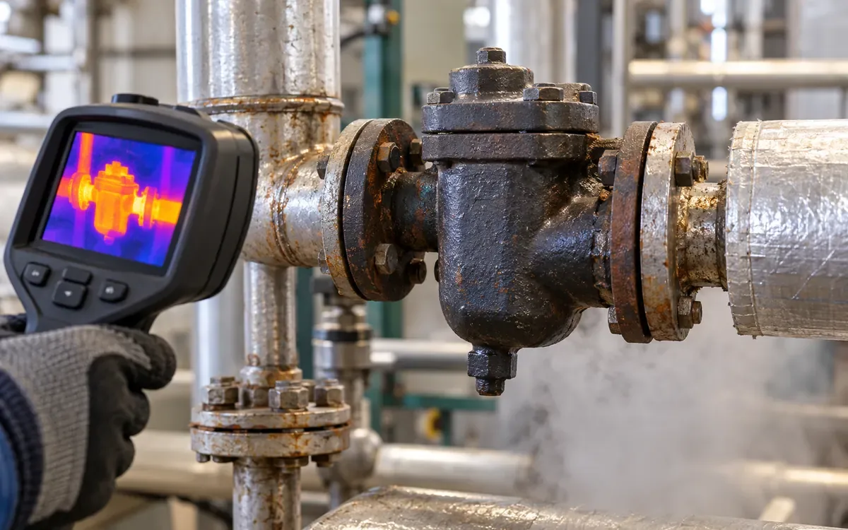
A camera can show a temperature pattern and help identify cold or abnormal areas. Temperature alone cannot separate live steam leakage from hot condensate and flash steam. Combine it with trap-specific diagnosis and service information.
Should every failed trap be replaced?
Follow the manufacturer's repair options and inspect the installation. Some units can be restored with approved internal parts; others are replaced as assemblies. A sound trap in a poor drainage system needs a system correction. The lowest purchase price does not establish the lowest installed cost.
Is a contractor's savings estimate enough for approval?
It is useful when its assumptions can be checked. Request trap IDs and the loss method. Check service hours, recovery boundary, variable steam cost, and repair scope. Have maintenance and finance review the same calculation. They should agree on both technical and cost assumptions.
Turn the survey into a repeatable maintenance result
Keep observations, diagnoses, and verified repairs distinct in the survey. It records traps that could not be tested. It uses realistic service hours and makes clear when leak estimates are uncertain. That discipline makes the repair budget easier to defend and the results easier to check.
Start with a reliable register and a short pilot route. Complete the route when the plant is in a suitable state. Resolve uncertain cases and retest the repaired duties. The value comes from sound drainage and lower losses. The evidence should support both results.
References
U.S. Department of Energy: Inspect and Repair Steam Traps.
TLV: A Guide to Steam Trap Testing.
Spirax Sarco: Testing and Maintenance of Steam Traps.
TLV: Is My Trap Leaking Live Steam?.
Spirax Sarco: Lifting Condensate and Contaminated Condensate.

Discussion0
Loading the discussion…