

Start with the conditions the factory must keep
A textile factory HVAC audit should answer two linked questions. Does the air system provide the conditions that production and people need? What energy is used to provide those conditions? A lower meter reading can be useful. The required service must remain intact.
Consider a weaving hall. Its corners are warm but the central aisle is cold. Humidity rises after lunch. Raising the fan speed may hide one symptom while making another worse. The cause could be poor air distribution or a wet process load. A sensor may be wrong. Outdoor air may enter through open doors. Each cause needs a different response.
Begin with a zone map and a written service need. Record the accepted temperature and humidity range for each process. Identify who approved it and what evidence supports it. Include occupied hours, exhaust needs, and product limits. Note when materials stay in the room without workers. Do not assign one relative humidity target to every textile operation.
This audit follows the air from the outdoor intake to the work area and back. It covers fans, ducts, filters, coils, dampers, humidifiers, exhaust, and controls. A chilled-water plant needs a separate efficiency assessment. Its meter reading alone cannot explain a poor air pattern inside a hall.
Separate three duties before collecting data
An air handler may serve people, the textile process, and the building. Write each duty separately. Check that a change keeps every required service.
Duty | What the audit must establish | Evidence to collect |
|---|---|---|
Process conditions | Keep temperature and moisture within limits | Zone trends. Process limits. Quality events. |
General ventilation | Supply required outdoor air to occupied areas | Design basis. Outdoor flow. Occupancy. |
Source control | Dust, vapour, or heat is captured where it is released | Exhaust drawings, hood checks, exposure assessment |
Building pressure | Keep air moving in the intended direction | Air balance. Pressure readings. |
Off-shift protection | Protect stored goods and equipment | Shutdown limits. Overnight trends. Restart test. |
General room air circulation does not prove that a dust source is controlled. The IFC textile manufacturing guidelines discuss enclosure and local exhaust for dust-producing equipment. These functions need their own checks when an energy project changes airflow.
Give every zone an owner. Production should confirm the process range. The safety team should confirm ventilation and exposure controls. Maintenance should confirm how the installed system delivers them. Record unresolved conflicts before selecting a savings measure.
Build a useful test plan
Choose readings around a question, not around the tools available. Suppose humidity rises after the shift starts. Log outdoor, return, supply, and room conditions. Use the same times for all readings. Add door use, process activity, and humidifier command. These records can separate a moisture source from a control fault.
Plan temperature and humidity logging. Measure airflow, pressure, and fan input power. Add control trends. Record each instrument and its calibration status. Add location, sampling interval, and units. Keep original data alongside any cleaned file.
Place room sensors at typical work locations. Avoid direct supply jets, sunlight, and wet surfaces. Keep clear of nearby motor heat. Place sensors there only when studying those effects. A return-grille sensor may describe the average return air. It can miss a hot operator position.
Measure several operating states. Include startup and normal output. Cover busy production and breaks. Add an off-shift period where relevant. Extend logging to cover weather that creates the suspected problem. A cool morning inspection cannot establish performance during a humid afternoon.
Align clocks before logging. A five-minute clock error can reverse the apparent order of events. A damper may seem to move after the temperature change it caused. Mark temporary sensor moves and manual overrides in the event log.
Use moisture content as well as relative humidity
Relative humidity compares vapour pressure with saturation pressure at the same temperature. It changes with temperature. The water vapour per unit of dry air may stay constant. A falling relative humidity reading does not prove that moisture left the room.
Humidity ratio is usually written W. Its units are kilograms of water vapour per kilogram of dry air. Dew point provides another useful view of moisture. Enthalpy combines sensible and moisture-related energy on a stated mass basis. ASHRAE's psychrometrics chapter defines these properties. It explains how to balance moisture and energy in air systems.
For an audit, plot both temperature and relative humidity. Use a suitable psychrometric tool to find humidity ratio and enthalpy. Enter the correct local pressure. Check whether the tool reports grams or kilograms of water per kilogram of dry air. Confusing those units creates a thousandfold error.
Keep the results tied to physical events. Suppose room temperature falls while relative humidity rises. Humidity ratio stays steady. The main change may be sensible cooling. Humidity ratio may rise after a wet process starts. Check the source and the rate of moisture removal.
Work through an outdoor-air load example
The following values describe a hypothetical hall. They show an audit calculation. They are not textile process design conditions.
Assume outdoor air has an enthalpy of 82 kJ per kilogram of dry air. Return air has 53 kJ/kg. The air handler moves 10 kg of dry air per second. Outdoor air accounts for 25% of that dry-air flow. Ignore small heat gains before mixing.
Mixed-air enthalpy = outdoor fraction × outdoor enthalpy + return fraction × return enthalpy.
Mixed-air enthalpy = 0.25 × 82 + 0.75 × 53 = 60.25 kJ/kg.
The extra load caused by replacing return air with outdoor air is:
Outdoor-air load = 10 × 0.25 × (82 − 53) = 72.5 kW of thermal load.
Suppose measured humidity ratios are 0.021 kg/kg outdoors and 0.012 kg/kg in the return. The incoming moisture above the return-air basis is:
Moisture load = 10 × 0.25 × (0.021 − 0.012) × 3,600 = 81 kg/h.
Both results refer to the assumed mass flows. They do not state the required ventilation rate. They also do not show electrical use. To estimate electricity, use actual cooling system performance. State which equipment the calculation includes.
A cool outdoor period can still be damp. The example shows the large moisture load this can create. It does not justify shutting the outdoor damper. First establish the required outdoor flow and exhaust replacement. Then check the measured flow. Is it above the approved need? Does air enter through an uncontrolled route?
Check airflow with a mass-balance mindset
Trace supply, return, outdoor air, and exhaust on one sketch. Mark which flows have been measured and which come from old drawings. Damper position is not airflow. A 30% command does not prove that 30% of the supply is outdoor air.
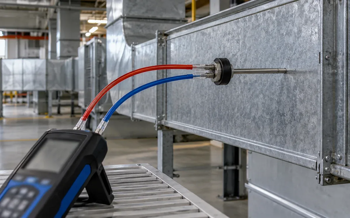
Use a suitable duct traverse or calibrated flow station. Choose a location with suitable flow conditions. One velocity reading at the duct centre rarely describes its whole area. Account for obstructions and follow the instrument's method. Compare like units and correct density where the method requires it.
At room level, a useful first check is supply minus return minus mechanical exhaust. The remaining flow must pass through other openings or reflect reading error. It is not automatically a leak estimate.
Consider a hypothetical room with 12.0 m³/s of supply air. It returns 9.5 m³/s and exhausts 2.0 m³/s. The simple residual is 0.5 m³/s. It could represent outward transfer through doors, reading uncertainty, or an unrecorded branch. Measure room pressure and inspect paths before calling it waste.
Compare branch totals with the main duct flow. A mismatch means the readings do not yet balance. Repeat suspect readings with stable fan operation before ordering duct repairs. Include access limits in the report rather than treating unmeasured branches as zero.
Find the distribution fault before raising fan speed
A room can receive enough total air and still have poor local conditions. Supply air may return too soon. A diffuser may be blocked. New equipment may divide a once-open hall. Check the air pattern where people and materials are located.
Create a grid of named points on the layout. At each point, record conditions during the same production state. Link complaints to locations and times. This makes a vague report such as “the far end is too warm” testable.
Inspect changes since the last balance. Check new partitions, stacked cartons, and signs. Moved machines can also change air paths. Confirm that movable stock does not block return routes. A balanced system at handover may no longer be balanced after a line change.
Measure filter and coil pressure drops against their approved service condition. Low pressure drop may mean clean equipment or low flow. It may also indicate bypass or a missing filter. A high reading can reflect loading or an incorrect component. Interpret it with airflow and physical inspection.
The DOE ventilation assessment guide includes testing, balancing, maintenance, and ventilation improvements. Its general building methods are useful here. Yet the factory needs its own design basis for process exhaust and textile hazards.
Read the control sequence as a story
Ask the controls technician to explain startup. Follow each step from the stopped system to stable production. Then compare that description with the actual program and trend data. Record when the fan starts and how the outdoor damper moves. Check supply temperature and humidity control. Include shutdown limits.
Look for commands that fight each other. A humidifier may add water while a cooling coil removes it. A space may need moisture removed without further cooling. That can require reheat. Poor coordination between control loops can also cause reheat. The operating reason matters.
ASHRAE's controls guidance explains humidity control. Cooling alone may not control moisture as the process needs. It also describes cases where reheat is needed after dehumidification. Find out why heating and cooling occur together. Do this before removing either function.
Check sensor location, scaling, and control direction. Compare a room humidity sensor with a suitable reference at stable conditions. Verify that the screen displays measured humidity rather than a fixed target. Check whether an alarm is disabled or repeatedly acknowledged without check.
Document override ownership. Give each temporary change a reason and expiry time. Check that the original state is restored. A trial may leave the system in manual mode. If staff forget to reset it, waste can persist.
Treat economizers and recovery as conditional options
An air economizer uses favourable outdoor conditions to reduce mechanical cooling. Favourable conditions depend on the process. Moisture may need tight control. Outdoor dry-bulb temperature alone may then be a poor guide.
The DOE HVAC retrofit guidance describes economizers, energy recovery, and demand-controlled ventilation. It also notes the importance of controls and damper maintenance. First check process conditions and contaminant sources. Then assess these options for the textile hall.
Consider two hypothetical outdoor periods at the same temperature. One is dry and the other humid. The dry period may help remove sensible heat without adding much water. The humid period may create extra dehumidification duty. A control strategy that treats them as identical can increase total energy use.
For heat or energy recovery, check leakage and carryover. Assess fouling and cleaning access. Check pressure between the streams. Dusty or chemical process exhaust differs from clean office exhaust. Assess it for its actual contaminants. Obtain a design review for the actual contaminant mix and equipment.
Occupancy-based control also has limits. Carbon dioxide may help assess ventilation for people. It does not measure textile dust or solvent vapour. HSE's textile dust guidance describes process hazards. Dust needs suitable controls. Keep those duties active whenever the relevant process requires them.
Calculate fan savings without promising a cube-law result
Measure electrical input at the chosen fan-system boundary. Record airflow, pressure, speed, filter condition, and production state at the same time. A lower fan reading may mean less airflow. Check that required air service remains intact.
Assume a hypothetical air handler draws 26 kW before balancing. After a controlled change, it draws 22 kW. All approved zone and ventilation conditions remain met. The stable reduction is 4 kW.
If this condition applies for 3,600 hours per year, the preliminary annual saving is:
Electrical saving = (26 − 22) × 3,600 = 14,400 kWh/year.
This estimate needs separate treatment of other operating states. It also excludes any change in cooling, heating, or humidification. Add those effects only when the measurement or model supports them.
Fan affinity laws can help assess a speed change. They apply to the same fan under suitable conditions. They do not guarantee a cube-law result for total motor input. Check the actual operating point. System resistance, controls, efficiency, and minimum ventilation constrain the actual result. Use the measured service and power together for acceptance.
Test scheduling without damaging the morning start
The factory schedule is more detailed than occupied or empty. Identify cleaning, maintenance, material storage, late production, and early preparation. Some areas can relax their conditions overnight; others cannot.
The DOE facility energy checklist links HVAC operation to need. It also calls for review of warmup and setback controls. The schedule must also preserve the agreed textile process range.
Run a monitored trial on a suitable day. Record room conditions at shutdown and overnight extremes. Note restart time and time to stable conditions. Check first-batch quality. Include outdoor weather. Set a clear rollback rule before the trial starts.
Suppose reducing operation saves 18 kWh overnight but adds 7 kWh during recovery. The net energy reduction is 11 kWh for that cycle, before any other effects. Counting only the avoided runtime would overstate the result. A schedule may save energy but delay production. Include that effect in the decision.
Turn symptoms into testable questions
Use the table below to guide check. It suggests checks, not diagnoses from symptoms alone.
Observed symptom | Question to resolve | Useful paired evidence |
|---|---|---|
Humidity rises after doors open | Is outdoor moisture entering? | Door events, outdoor and room humidity ratio |
One aisle stays hot | Is supply reaching the occupied zone? | Local temperature map and diffuser flow |
Fan power rises each week | Is resistance or required flow changing? | Filter pressure drop, airflow, speed, power |
Cooling and humidification run together | Is the control sequence justified? | Moisture target, valve commands, supply conditions |
Room pressure changes with production | Does process exhaust lack replacement air? | Exhaust status, supply flow, room pressure |
Conditions recover slowly each morning | Is restart timing adequate? | Overnight drift, recovery trend, production start |
For every suspected cause, write down what would disprove it. The loading door may be blamed. Check similar periods with the door closed. If the problem persists, expand the check instead of keeping the first explanation.
Keep reading uncertainty visible
A small flow imbalance can disappear within the reading error. Treat that as a limit on the conclusion, not a reason to discard the survey. The result may still identify where a better measurement would help.
Return to the hypothetical room with 12.0 m³/s supply, 9.5 m³/s return, and 2.0 m³/s exhaust. Assume each reading has a bound of plus or minus 5%. This applies only to the example. The absolute bounds are 0.60, 0.475, and 0.10 m³/s. Adding them gives a conservative possible residual error of 1.175 m³/s.
The apparent 0.5 m³/s surplus is smaller than that bound. It does not prove the room has outward transfer. A statistical result could be narrower. But its assumptions need support. This includes the error distributions and whether errors are independent. The three readings may share a calibration bias. In that case, a simple square-root formula may be wrong.
Improve the weakest part of the test setup. A poor traverse location may matter more than buying a meter with a finer display. Repeat the survey at stable flow. Check dimensions and the method. Compare room pressure too. A small residual may decide the action. If so, commission a more suitable measurement.
Apply the same care to humidity comparisons. Two sensors that differ by two percentage points may have overlapping uncertainty. Check them side by side before concluding that the room has a moisture gradient. Return them to their mapped locations. Does the difference follow the position or the instrument?
Use a controlled trial sheet
Prepare a one-page sheet for each proposed change. Name the affected zones and the operating condition. List the readings to collect before, during, and after the trial. Record the original settings so that reset is quick and exact.
Consider a hypothetical fan trial. Stop rules could include a humidity excursion or loss of approved exhaust flow. An unsuitable pressure change at a door could also stop the trial. These limits must come from the site's approved needs. They should not be improvised after the first complaint.
Assign one person to make the change and another to watch the service conditions. Tell production when the trial begins. Log unusual events, such as a line stop or open loading door. They may cause a change that looks like a response to the trial.
Review the trial evidence. Adopt the change, take more readings, or restore the old setting. Keep an unsuccessful trial in the record. A lower fan setting may fail at one operating state. Keep that finding for future control design.
Specify what a successful correction must prove
Set acceptance conditions before making the change. Include the process range and required airflow. Check exhaust performance and pressure relationships. Define alarm response and the energy boundary. State how long the trial must run. List the production and weather states it must cover.
Keep the audit findings in a short action register. Record the defect and evidence in each entry. Add the proposed fix and owner. State the cost basis, expected saving, and verification method. Separate confirmed faults from ideas that need more measurement.
Use the factory utility load register when new equipment changes service demand. Update the air balance and control sequence after the equipment is installed. A new exhaust connection can change room pressure. Adequate electrical capacity does not prevent that effect.
Record the final settings and keep a recovery copy of the controls. Train the people who will operate them. Add recurring checks to the maintenance programme. Define when to recheck air balance or sensors.
Frequently asked questions
What humidity should every textile factory use?
One target cannot suit every fibre and process. The building and stored product also matter. Use an approved process need and evaluate worker conditions separately. A copied humidity number is not a substitute for that evidence.
Can a portable humidity meter replace long-term logging?
It can help check a sensor and map a stable condition. It cannot show overnight drift or a short event that occurred before the visit. Use spot checks and trends for their different purposes.
Does a high outdoor-air load mean outdoor air should be reduced?
Only excess or uncontrolled airflow is a candidate for reduction. Required ventilation, process exhaust replacement, and pressure control still apply. Confirm those needs before changing the system.
Should all simultaneous cooling and heating be removed?
No. Some systems need reheat to control temperature after moisture removal. Check why the sequence is needed. Can a better arrangement provide the same service with less energy?
How should the audit rank improvements?
Address verified service failures first. Then compare credible energy savings and installed cost. Assess disruption and reliability. Check whether staff can manage the controls. Keep uncertain savings visible rather than presenting them as guaranteed returns.
Conclusion
A useful textile HVAC audit connects each energy finding to an air service. It measures conditions where work happens. It reconciles flows and checks moisture as well as temperature. It also tests the actual control sequence. The result should explain both the fault and the evidence that a correction will work.
Start with a small number of well-defined questions. Resolve them with time-aligned readings and controlled trials. The strongest improvement keeps production conditions stable and ventilation effective. Its energy result can be traced to a clear change.
References
ASHRAE, 2025 Handbook—Fundamentals: Psychrometrics.
ASHRAE, 2023 Handbook—HVAC Applications: Design and Application of Controls.
US Department of Energy, Ventilation Assessment and Action Guide, 2025.
US Department of Energy, HVAC Retrofit.
US Department of Energy, Facility Energy Checklist.
IFC, Environmental, Health, and Safety Guidelines for Textile Manufacturing, 2007.

Discussion0
Loading the discussion…