
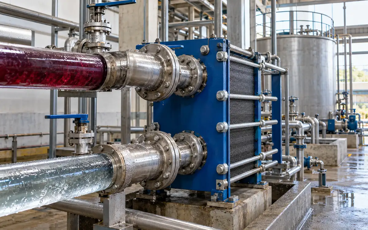
Find a useful heat destination before choosing equipment
Hot dyeing effluent can carry heat that the next process needs. A recovery project works when that heat reaches a suitable load at the right time. A large drain flow alone does not prove a good project.
The first task is to pair a source with a receiver. Record the hot stream's flow and temperature. Then find water that needs heating during the same period. Check whether that water can accept the recovered temperature and still meet the process specification.
The IFC textile manufacturing guidelines identify heat exchange from hot batch-dyeing effluent as an energy measure. This guide turns that opportunity into a practical balance and a testable business case.
All numerical cases below are hypothetical. They illustrate design review and measurement. The final equipment needs verified stream data, a suitable materials assessment and a supplier's detailed rating.
Keep heat recovery distinct from water reuse
An indirect heat exchanger transfers heat through a wall. The dirty effluent and clean water follow separate routes. Heat recovery does not, by itself, make the effluent fit for reuse.
Keep the clean-water quality requirement in the design. A leak across the wall could affect that quality. Select the separation, pressure arrangement, leak detection and response to match the actual process risk. A designer may need more than a single wall in some duties.
Continue to route the spent effluent to the required treatment system. Cooling it may change the treatment inlet condition, but it does not remove dyes, salts or other pollutants. Review the new flow and temperature with the treatment team.
Also distinguish this project from steam-condensate return. Dyeing effluent has been in the wet process. Indirect heating condensate follows another quality and recovery route. Combining their mass or heat totals without a clear boundary makes both business cases unreliable.
Map the hot streams before they mix
Start at the machines. List the drains that could supply heat and the process step that creates each one. Measure temperature at the proposed collection point, not only on a machine display.
Mixing a hot drain with a large cold flow can reduce its useful temperature. A smaller segregated stream may be more valuable than a larger mixed one. Review any proposed segregation with production and wastewater staff so it does not upset treatment or drainage.
Record each stream's timing. Batch drains may arrive as short bursts. A daily average flow can hide a high short-term flow that determines pipe and tank size.
For chemistry, collect the information needed for materials and cleaning choices. Include pH range, salts, suspended fibres and relevant process chemicals. One sample from a mild rinse may not represent a hot spent bath.
The Australian Government's waste-heat guide recommends assessing variations in temperature, flow and contaminants. Use that approach to build a duty range, rather than a single favourable design point.
Define the receiving water demand
Identify where preheated water will go. Possible receivers include suitable process-water tanks or other approved heating duties. The receiving process sets the acceptable temperature and quality.
Ask whether it needs hot water when the effluent is available. Check weekends, recipe changes, cleaning periods and low production. A receiver that disappears for half the year cannot support a full-year savings claim.
Determine what currently heats that water. Recovered heat may replace boiler steam, electric heat or another recovered source. Its value depends on what is actually displaced.
Avoid forcing water into a process just to use the heat. Extra water use may add treatment cost and change the recipe. The recovery design should serve the required process, with no assumed increase in useful demand.
Use ApparelDiary's liquor-ratio and dosing guide for the process-water basis. Keep recipe decisions separate from the utility heat balance developed here.
Write the two-sided heat balance
For a liquid with no phase change, the heat rate is:
Q = m × c_p × temperature change.
Use mass flow m in kg/s and heat capacity c_p in kJ/kg·K. The result Q is kW. A temperature difference in kelvin has the same numerical value as a difference in degrees Celsius.
The hot-side loss is m_hot × c_p,hot × (T_hot,in − T_hot,out). The cold-side gain is m_cold × c_p,cold × (T_cold,out − T_cold,in).
For a steady exchanger with small external losses, those duties should be close. The Alfa Laval heat-transfer guide describes this balance and the required flow and temperature inputs.
If flow is measured in m³/h, convert it with the relevant density. Do not mix kilograms per second with kilograms per hour. State any water-like property assumption for the effluent. Strongly loaded streams may need measured or calculated fluid properties.
Solve an original textile-plant example
Assume a proposed recovery stage has steady, simultaneous flows. Treat both streams as water-like liquids with constant c_p = 4.18 kJ/kg·K. Ignore external heat loss for the first calculation.
Input | Hypothetical value |
|---|---|
Hot effluent mass flow | 18,000 kg/h |
Hot inlet temperature | 78°C |
Proposed hot outlet temperature | 43°C |
Clean-water mass flow | 15,000 kg/h |
Clean-water inlet temperature | 25°C |
Hot flow is 18,000 ÷ 3,600 = 5 kg/s. The hot-side duty is:
Q = 5 × 4.18 × (78 − 43) = 731.5 kW.
Cold flow is 15,000 ÷ 3,600 = 4.1667 kg/s. The required cold-water temperature rise is:
731.5 ÷ (4.1667 × 4.18) = 42 K.
The resulting cold outlet is 25 + 42 = 67°C. This is a balance result. It does not prove that a chosen exchanger can achieve it. The next checks test temperature differences, heat-transfer area and pressure loss.
The process must also accept water at 67°C. If its approved maximum is lower, the receiver or controls impose a different duty. The thermal calculation cannot override the process requirement.
Check the temperature difference at both ends
Consider true counterflow: the two streams travel in opposite directions. At one end, hot inlet meets cold outlet. At the other, hot outlet meets cold inlet.
For the example, the end differences are:
ΔT_1 = 78 − 67 = 11 K.
ΔT_2 = 43 − 25 = 18 K.
Both are positive. The proposed temperatures therefore pass this basic direction check. The cold outlet can exceed the hot outlet in counterflow because those outlets occur at opposite ends.
A passive exchanger cannot heat the cold stream above the hot inlet under the stated simple conditions. A proposal that does so has a missing heat source, a timing issue or a calculation error.
The DOE waste-heat recovery report explains why source temperature and the gap to the receiver matter. Heat quantity alone is not enough. A small driving difference needs more heat-transfer area for the same duty.
Use the right mean temperature difference
For the stated counterflow case, use the logarithmic mean temperature difference, LMTD:
LMTD = (ΔT_2 − ΔT_1) ÷ ln(ΔT_2 ÷ ΔT_1).
Here, LMTD = (18 − 11) ÷ ln(18 ÷ 11) = 14.21 K.
The ASHRAE heat-transfer chapter sets out this method and its assumptions. They include a suitable steady flow pattern, constant overall coefficient and heat capacities, and negligible external loss.
If the two end differences are equal, LMTD equals that common value. The written formula gives an indeterminate form at exact equality, so software needs to handle that limit correctly.
Other flow arrangements may need a correction factor or another rating method. Do not apply an ideal counterflow result to a multi-pass design without checking it. Ask the supplier to identify the actual flow arrangement and the method used in the rating.
Treat area as a design check, not a purchase specification
The basic heat-transfer relation is Q = U × A × LMTD. Here U is the overall coefficient, A is the related transfer area and Q is expressed in watts when U is in W/m²·K.
Assume, for illustration, a design U of 750 W/m²·K. The example needs:
A = 731,500 ÷ (750 × 14.21) = about 68.6 m².
This is a hypothetical coefficient, not a textile-effluent standard. A real value depends on the fluid, flow path, velocity, wall and deposits. If the design coefficient were 550 W/m²·K, the same stated duty and temperatures would require about 93.6 m².
Spirax Sarco's heat-transfer explanation describes how the wall, fluid films and fouling contribute to resistance. That is why a catalogue area cannot establish field duty on its own.
The supplier must also check flow distribution, pressure drop, cleanability and mechanical limits. Adding plates or surface without checking flow velocity can change performance in ways the simple area formula does not show.
Use effectiveness to explain the thermal result
The maximum ideal duty for this simple two-stream case is:
Q_max = smaller heat-capacity rate × (T_hot,in − T_cold,in).
A heat-capacity rate is mass flow multiplied by heat capacity. The cold stream has the smaller value in the example: 4.1667 × 4.18 = 17.4167 kW/K.
Q_max = 17.4167 × (78 − 25) = 923.08 kW.
Effectiveness = actual duty ÷ Q_max = 731.5 ÷ 923.08 = 0.792, or about 79.2%.
This is a defined exchanger measure. It is not the percentage of the mill's fuel bill saved. It also differs from the percentage of all effluent heat captured over a year.
Use the name and denominator whenever a supplier quotes “recovery efficiency.” Ask whether it means exchanger effectiveness, hot-stream cooling, annual capture or fuel reduction. Each can be useful, but the values answer different questions.
Model the batch schedule before annualising duty
The steady example assumes both flows exist together. A batch mill needs to test that assumption against its schedule.
Create short time intervals with hot flow, hot temperature, cold demand and cold inlet temperature. Calculate a valid useful duty for each interval. Sum duty multiplied by time to obtain recovered energy.
Do not multiply a peak duty by all factory working hours. The exchanger may spend some hours waiting for a drain or a receiver. Other hours may have lower inlet temperatures or restricted flow.
For an early model, use equivalent full-duty hours. These are annual useful energy divided by the stated full duty. Label them clearly. They are not necessarily the hours when a pump is switched on.
For example, 1 hour at 700 kW and 1 hour at 350 kW recover 1,050 kWh of heat. That equals 1.5 full-duty hours at 700 kW. It does not equal two full-duty hours merely because the plant ran for two hours.
Assess storage as a separate engineering choice
A tank can shift recovered heat from one period to another. It can also add cost, heat loss, mixing and cleaning needs. Choose it from the schedule rather than adding a large tank by habit.
For a simple screening case, suppose 6,000 kg of clean water stores a 20 K rise. At c_p = 4.18 kJ/kg·K, stored sensible heat is 501,600 kJ, or 139.3 kWh. This assumes a uniform usable temperature and ignores tank losses.
That quantity can support 278.7 kW for half an hour in an ideal balance. It cannot support the example's 731.5 kW duty for a full hour. The arithmetic helps test whether storage can bridge the actual mismatch.
The real usable amount depends on minimum delivery temperature and tank flow pattern. Mixing can lower the useful outlet before all stored heat is used. Include insulation, access, water-quality control and the process response when the tank is empty or too cool.
Choose an exchanger around the dirty-side duty
Compare suitable designs using the same stream data. Plate, wide-gap, tubular or other arrangements may each suit a different fouling and access problem. There is no single best type for every dyehouse.
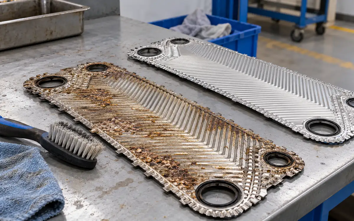
Ask how the proposed passages handle fibres and deposits. Define screening or filtration needs and the pressure loss when those devices become dirty. A filter adds maintenance and waste handling; it does not make all dissolved contaminants disappear.
Check materials against the actual chemistry and temperature range. Include gasket exposure and cleaning chemicals where relevant. A material selected from a clean-water example may not suit a concentrated process drain.
Make the supplier state clean and design performance. Ask how the design allowance was chosen and what field evidence supports it. Avoid treating a clean-water heat-transfer coefficient as a guaranteed dirty-effluent value.
Reserve space for maintenance. Check how plates or tubes are accessed, where rinse water goes and how the system returns to service. A unit that is difficult to clean may lose useful duty long before its planned service life ends.
Calculate the annual fuel and cost case
Assume the example delivers 731.5 kW for 3,200 equivalent full-duty hours per year. Useful annual heat is:
731.5 × 3,200 × 0.0036 = 8,426.88 GJ.
The factor 0.0036 converts kWh to GJ. Suppose this heat displaces boiler-supplied heat with an effective marginal fuel-to-receiver efficiency of 0.82.
Avoided fuel = 8,426.88 ÷ 0.82 = 10,276.68 GJ per year.
At an assumed fuel price of 9 currency units per GJ, gross benefit is about 92,490. Use an efficiency that fits the displaced duty. Do not count distribution losses again if they are already included in that factor.
Assume added pumps draw 6 kW during 3,200 hours. At 0.12 currency units per kWh, added electricity costs 2,304. Allow 3,600 per year for cleaning and service. Net benefit is about 86,586.
For a complete installed cost of 118,000, simple payback is 118,000 ÷ 86,586 = about 1.36 years. These prices and hours are invented teaching inputs. They are not a promise of local fuel rates or typical project returns.
Test the hours and cleaning assumptions
If useful duty occurs for only 1,800 equivalent hours, the result changes sharply. At the same full duty and prices, net annual benefit falls to about 47,130. The simple payback becomes about 2.50 years.
This lower-hours case assumes pump hours also fall to 1,800, while the annual service allowance stays at 3,600. If pumps run while no heat is useful, their cost would be higher. Include that behaviour in the actual model.
Also test lower heat transfer between cleanings. A declining U value changes achievable duty and outlet temperatures. Do not hold every output fixed while reducing U in a performance model for installed equipment.
Include bypass periods, cleaning chemicals, labour, replacement seals and disposal costs as relevant. Count lost production only if the recovery system truly creates it. Show grants or tax effects separately from the equipment's operating benefit.
Check a warmer season before fixing the guarantee
Cold-water temperature may change during the year. That changes the driving force even when hot effluent stays the same. The purchase specification should include the expected inlet range on both sides.
For example, raise the cold inlet from 25°C to 32°C. Retain the original flows and imagine that the exchanger still delivers 731.5 kW. The same 42 K rise would make the cold outlet 74°C. With a hot inlet of 78°C, the hot-end difference would now be only 4 K.
That result demands a much closer approach than the original 11 K. It cannot be assumed for the same exchanger without a new rating. If the process also limits the clean water to 67°C, its accepted duty is lower for another reason: it now needs only a 35 K rise.
At 15,000 kg/h and the same heat capacity, that receiving duty is about 609.6 kW. It becomes a process limit even if the exchanger could transfer more. Controls must respect the limit, and the annual model must use the useful heat rather than the original nameplate duty.
Ask for a small rating table covering the normal, warmer-inlet and low-flow cases. It makes the seasonal risk visible before purchase. It also gives operators valid reference points when the outlet temperature changes in service.
Specify controls for useful and safe operation
The system needs a response when either stream is absent. It also needs limits for water temperature, pressure and flow. Define those responses with the designer and the process team.
Keep essential machine drainage available when recovery equipment is out of service. A recovery fault should not force operators to improvise a drain route. The approved design should provide the needed bypass and status indication.
Protect the receiving process from overheated or suspect water. Define detection, isolation and any hold decision for a possible cross-leak. Make the response visible to the people responsible for water quality.
Record the added electrical and hydraulic duties in the factory utility load register. The recovery package changes pump loads and pipe conditions even when it reduces steam use.
Measure useful heat after commissioning
Measure both flows and all four temperatures where practical. Use suitable sensor locations and matched time stamps. The cold-side gain provides direct evidence of heat delivered to the receiver.
Compare it with the hot-side loss. If they differ greatly, check heat loss, timing, meter range, fluid properties and mixing. Do not force the two numbers to agree by changing a constant without evidence.
Track useful heat delivered after any storage or distribution loss that belongs inside the savings boundary. Heat entering a tank is not always equal to heat reaching the process.
Record baseline and post-project purchased heat or fuel over matched duties. Explain changes in production, inlet water temperature and recipes. A rising production volume can hide a successful project in the monthly fuel bill. A falling volume can make an ineffective project look successful.
Use trends to guide cleaning and fault finding
Observed change | Evidence to check next |
|---|---|
Lower heat duty at matched inlets | Flow change, deposits, bypass position or sensor error. |
Higher dirty-side pressure loss | Screening condition, blocked passages or altered viscosity. |
Warm water when no process needs it | Schedule mismatch, tank control or unused heat. |
Unequal hot and cold balances | Timing, density, heat loss or meter error. |
Suspect clean-water quality | Cross-leak assessment and the approved isolation response. |
Define a clean reference test. Repeat it at comparable flow and inlet temperatures after cleaning. A warmer clean-water inlet can reduce duty even when the exchanger is clean, so raw outlet temperature alone is a weak fouling indicator.
Keep the records with the maintenance programme. Link cleaning effort to restored useful duty and pressure loss. That record helps improve the interval and exposes designs that need too much service.
Frequently asked questions
Can recovered heat replace all dyeing heat?
Usually the receiver still needs further heating or another heat source. The available flow, source temperature and timing set the limit. Calculate the actual useful duty before assigning a fuel reduction.
Does a 79% effectiveness mean a 79% fuel saving?
No. It compares exchanger duty with a defined two-stream thermal maximum. Annual fuel reduction also depends on capture hours, process demand and the displaced heat source.
Is a lower effluent outlet always better?
Only if the extra heat has a useful destination and the whole system remains suitable. A smaller temperature approach can require more area and cost. Review the treatment inlet condition as well.
Should the mill buy equipment from average daily flow?
Use averages for annual totals, but also check batch peaks and periods of no flow. Pipes, tanks, screens and exchanger passages must handle their actual operating range.
Build the project around a measured heat match
A good recovery project links a real hot stream to a real heating need. It checks both sides of the balance, both end temperatures and the hours when the match exists. It also gives fouling, quality protection and maintenance a place in the cost case.
Keep those boundaries clear through design and commissioning. The result is a defensible measure of heat delivered and fuel avoided, with no need to treat all heat in a drain as an automatic saving.
References
IFC: Environmental, Health and Safety Guidelines for Textile Manufacturing.
Australian Government: Waste Heat Recovery.
Alfa Laval: The Theory Behind Heat Transfer.
Discussion0
Loading the discussion…