
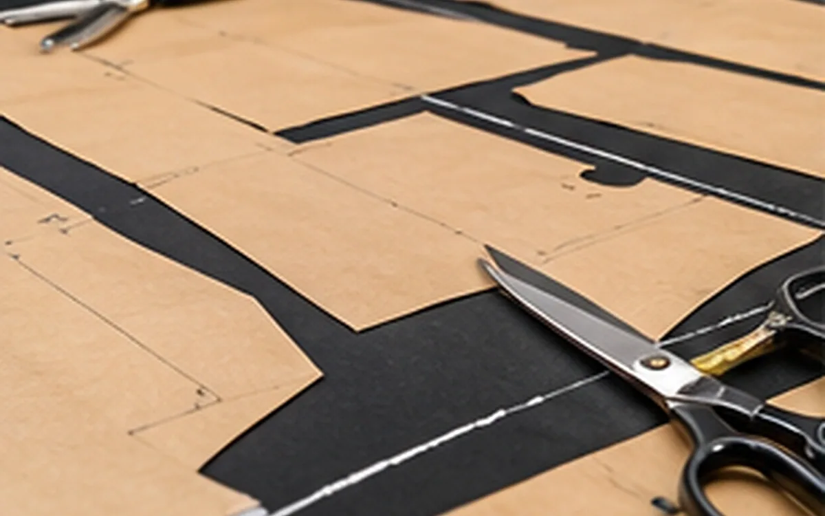
A pattern tool earns its place by helping someone draw, measure, copy or cut a defined shape. A large kit does not make those tasks accurate on its own. A worn ruler edge, a thick pencil line or a moving sheet can change the result even when the right tool is in your hand.
Choose pattern making tools around the work you need to do. Then check how they behave together on the paper and materials you use. This guide covers a manual drafting kit, with original exercises for straight measurements, curved lines and seam allowances. The dimensions are teaching examples, not approved garment specifications.
Build the kit around the job
Manual pattern work combines several tasks. Measuring sets dimensions. Drafting joins the points into a shape. Tracing copies that shape, while cutting produces an edge that someone else may follow. Marking adds the information needed to use the piece.
Each task needs a suitable tool, but some tools serve more than one purpose. A clear grid ruler can measure a straight line and help place a parallel line. It cannot, by itself, confirm the length of a curved armhole. A tape can follow a curve, but it does not provide the firm edge needed to draw a straight baseline.
The Skills England pattern-cutter profile connects drafting tools with measurements, pattern review and production information. It describes an occupation, not a shopping list for every workroom. Its useful lesson is that tools support a method and a product brief.
Task | Useful starting tools | What to check |
|---|---|---|
Set straight dimensions | Rigid ruler and square | Scale, zero point and edge condition |
Shape a curved line | French curve or longer curve rule | Suitable shape and smooth joins |
Copy a pattern | Tracing paper, pencil, weights or suitable wheel | Movement, line identity and transfer quality |
Cut paper or card | Suitable scissors or cutter | Material range, control and clean edges |
Add production marks | Fine marker, notcher or point tool where approved | Mark position, meaning and depth |
Start with the tools needed for current work. A special curve, punch or heavy card cutter becomes useful when a repeated task justifies it. Check the actual model's instructions before using it on a new material. The name of a tool family does not define every product's limits.
Read the scale before trusting the length
A rigid ruler gives a stable scale for flat paper. Choose a length that reaches across the main measurement where practical. Several short measurements can work, but each move introduces another point that must be aligned and read correctly.
Look at the ruler's zero mark. Some scales begin at the physical end; others start in from it. A chipped end makes that distinction more important. Align the pattern reference with the marked zero, not with an edge that merely looks like the start.
You can also measure between two clear scale marks. Suppose a paper line starts at 20 mm and ends at 200 mm. Its length is 200 − 20 = 180 mm. Reading the endpoint alone would add an error of 20 mm. Record the difference, and use a sound ruler rather than making a damaged tool the normal method.
Keep the scale close to the paper and look directly at the mark you are reading. Thick tools, an angled view and a broad mark can make the alignment hard to judge. Decide which part of the drawn line represents the dimension. Changing from one edge of a thick line to the other changes the measurement.
Keep units visible
Metric and inch scales may sit on opposite edges of the same tool. Check which one is in use each time you turn it. A centimetre has ten millimetres; a decimal fraction of an inch is not a fraction of a centimetre.
NIST's length guidance gives the exact conversion of one inch to 25.4 mm. Thus, a specified length of 4.5 in equals 4.5 × 25.4 = 114.3 mm. Converting it to 114 mm is a rounding decision, not an exact conversion. The pattern requirement should decide whether that rounding is acceptable.
Similarly, 5/8 in equals 15.875 mm. A 16 mm allowance differs by 0.125 mm. Those numbers may be close for a particular task, but closeness does not give permission to replace the specified value. Keep one working unit where possible and state any agreed conversion.
Use a tape for the shape it can follow
A flexible tape helps with body measurements and curved paths. Utah State University Extension recommends a firm, flexible tape that does not stretch. That combination matters: a tape must bend to the path without changing its own length under the measuring force.
For a curve, place the tape along the defined line without pulling it tight or bridging across a hollow. Work in manageable sections and keep the starting point fixed. A tape laid between the endpoints measures their direct distance if it does not follow the curve.
Compare a suspect tape with a suitable reference along several parts of its scale. Check the zero end as well as a longer interval. Agreement over a short section does not establish that the whole tape is sound. Kinks, worn numbers or a loose end fitting can make the working method unclear even before a scale error is considered.
Use a small ruler or seam gauge for repeated short offsets where it gives better control. Reset and check a sliding gauge before relying on it. The convenient tool is the one that holds the required setting during the actual task, rather than the one with the most features.
Establish straight lines and right angles
A straightedge controls a line; a square adds a right-angle reference. Set the square against a known straight baseline. If that baseline is curved, torn or covered by a raised tape repair, the square can sit differently each time.
Check for visible damage and rocking before use. A simple reversal check can reveal a problem: draw a perpendicular line from a chosen baseline point, flip the square to the other side, and draw again from the same point. The two lines should agree within the checking method's limits. Keep the paper and baseline fixed throughout.
If the lines diverge, investigate the square, the baseline, the setup and the drawing technique. Do not immediately label one tool accurate because another disagrees with it. The check identifies a question; it does not provide a traceable angle measurement or a certificate.
The National Physical Laboratory guide to measurement explains why required accuracy depends on the task. It also distinguishes calibration from simple checks before use. A workbench comparison can find an obvious fault, but formal measurement control needs a suitable reference, method and records.
For everyday drafting, agree how accurately the line must be placed and which reference will settle a disagreement. Avoid claiming tenths of a millimetre from a broad pencil mark and a scale that cannot support that reading. More decimal places in the note do not improve the drawing.
Let the curve rule join points, not invent them
French curves offer several short curve shapes. Longer hip or dressmaking curves can help with broader lines. The useful choice depends on the points and line directions that the pattern needs, rather than the name printed on the tool.
Prym's curve-rule description illustrates a tool designed for both rounded garment shapes and straight grid work. Those functions can save repositioning. They do not establish the correct armhole, neckline or hip shape for a person. The draft and approved design still define the required shape.
Mark the important points first. Place the curve so it agrees with the nearby points and the direction of the line as it approaches them. Draw only the portion that fits. Then move the tool to continue, overlapping enough of the previous section to judge the join.
A join can pass through the correct point and still form a kink. Check the direction on both sides, not only whether the two marks touch. View the whole curve after drawing it. Repeatedly correcting a short area can leave several competing lines, so erase or clearly cancel the rejected one.
Do not shift a fixed measurement point just to match a convenient part of the ruler. If the supplied points cannot form the intended smooth shape, resolve the draft or measurement issue. A smooth-looking line may still be the wrong length or in the wrong position.
Control the paper, pencil and holding method
Use paper that can support the work. A light tracing sheet may suit copying, while a reusable template may need a firmer material. Judge visibility, tear resistance and the way the chosen marker behaves on it. A thick card edge can also affect the position of a tracing line.
Make construction lines fine enough to distinguish from the final edge. A sharp pencil allows revision; a permanent pen may suit final labels after the shape is settled. Colour can help show changes, but written labels should carry the meaning. A photocopy or another reader may not preserve the colour distinction.
Hold the paper flat before measuring. Place clean weights where they prevent movement without hiding the line being traced. Move them in stages so the untraced section stays secure. If the sheet shifts, return to fixed reference marks and check the affected region instead of blending two positions into one outline.
Pins may be useful where holes are acceptable. Test their effect on the actual material and keep them away from the cutting path. A pin through several sheets does not guarantee that every layer remains aligned at a distant edge. Check the lower sheets rather than relying on the top outline alone.
Repair a working paper pattern without changing its geometry. Align the original reference lines before taping a tear. A repair that overlaps the paper removes length; one with a gap adds it. Copy a badly damaged piece onto sound paper once the intended shape has been confirmed.
Choose a cutting tool for the material
Paper scissors, fabric shears and cutters are not interchangeable merely because each can make a cut. Check the tool's stated use and the thickness you intend to cut. Label dedicated tools clearly so their condition and purpose are easy to recognise.
Test a small waste piece first. Look for a clean edge through the whole cut, including the tip region on scissors. Folding, tearing or pushing the material suggests that the tool, its condition or the technique needs attention. Extra force should not be the normal solution.
OLFA's cutter guidance stresses a suitable cutter, a stable work surface, a sound blade and a clear hand position. It also warns that thin or sloped ruler edges can let a knife ride up. A plastic drafting curve should not become a blade guide unless it is suitable for that use.
Use the cutting surface and guide specified for the tool. Keep the supporting hand out of the blade path, and secure or retract the blade when work stops. Instructions for snapping a segmented blade apply to that blade type; they do not apply to a rotary blade. Follow the product's replacement instructions.
Cut to the approved line consistently. Leaving a border on one side and cutting inside the line on the other can change the template even when the drawn dimensions were correct. Check important dimensions again after cutting, especially where a later tracing will follow the cut edge.
Transfer marks with the least damage needed
A tracing wheel transfers a path through contact with the layers below. The wheel type and the transfer material determine what it leaves. Pressure alone does not turn an unsuitable wheel into the right one.
Clover's tracing-wheel guide distinguishes a serrated wheel designed to penetrate from a blunt wheel intended for use with transfer paper. A punctured line and a removable transferred line are different results. Choose the result the work requires, and test the full layer arrangement first.
Check both the source pattern and the receiving sheet after the test. The line should be clear enough to follow without unnecessary damage. A transfer paper that works on plain drafting paper may behave differently on coated card or fabric. Keep any fabric marking test separate from permission to punch through the material.
An awl or other point tool can identify an internal location in a paper template. A notcher can make an edge reference. Neither decides what the mark means. Confirm its location and function before making an irreversible hole or notch. Use a suitable backing, keep hands clear and work within the tool's intended material range.
The notch made in a card pattern does not set the required cut depth in fabric. Likewise, a paper hole marking a dart location is not an instruction to drill the garment. The production method must define how each reference is transferred.
For chalk, pens or other fabric markers, test removal on a scrap from the actual material. Include the relevant handling or pressing step if it may affect the mark. USU's guidance supports checking removability before use. A visible mark that cannot be removed may be more damaging than one that was slightly harder to see.
Exercise one: draft and check a rectangular pocket
Use this fictional paper exercise to test the basic kit. It assumes a rectangular pocket with finished dimensions of 160 mm wide by 220 mm high. Add 10 mm at each side, 10 mm at the bottom and two 15 mm turns at the top. Ignore fabric thickness and turning effects for this geometry exercise.
The required paper rectangle is:
Cut width = 160 + 10 + 10 = 180 mm.
Cut height = 220 + 10 + 15 + 15 = 260 mm.
These allowances are chosen for the exercise. They are not a recommended pocket construction for every fabric. A production pocket needs a tested method and its own specification.
Draw a straight baseline, then use the square to establish one side. Mark the width and height from the chosen origin. Complete the rectangle and check opposite sides. Recheck the square after moving it; a correct first corner does not prove the next placement was correct.
Mark the two top-fold lines at 15 mm and 30 mm from the top cut edge. Mark the side and bottom turn lines at 10 mm. The distance from the second top-fold line to the bottom turn line is 260 − 30 − 10 = 220 mm. The width between side turn lines is 180 − 10 − 10 = 160 mm.
Now trace a separate copy. Align and secure the sheets, keep the line fine and identify the final cutting edge. Cut the copy, then compare it with the draft at the baseline, corners and turn lines. This sequence checks more than ruler reading: it reveals movement and cutting errors too.
Suppose a traced width measures 181 mm. The difference from the intended 180 mm is 1 mm. Before trimming it, find whether the extra width came from the drawn line, the tracing position or the cut. Correcting the wrong stage can leave the current piece usable while the same error returns on the next copy.
Exercise two: compare a curved path with its shortcut
For a separate paper exercise, draw a quarter-circle with a radius of 40 mm using a suitable compass or a verified template. The purpose is to test how you measure a curve, not to design a garment seam.
The arc length of a quarter-circle is π × radius ÷ 2. At a 40 mm radius, that is about 62.83 mm. The straight line between its endpoints is the chord. Its length is the square root of 40² + 40², or about 56.57 mm.
The difference is about 6.26 mm. A tape pulled straight between the endpoints would miss that length even if its scale were correct. Follow the curved path and compare the result with the calculated value, allowing for the drawing and reading method. Do not call the difference a tape error until the setup has been checked.
You can use the same drawing to examine a curve rule. Find sections that follow the arc, then practise making smooth joins without moving the endpoints. A general French curve may not match the exact circle over the whole length. That limitation is useful to see before treating its edge as a universal shape.
Next draw a concentric quarter-circle with a radius of 50 mm. It lies 10 mm outside the first arc. Its length is about 78.54 mm, which is 15.71 mm longer than the inner arc. Adding a 10 mm offset has not added just 10 mm to the curved length.
This explains why the line being measured matters when a pattern includes seam allowances. The cutting edge and sewing line can have different lengths. Use the intended line when comparing joined pieces, then check any required ease or shaping under the approved pattern method.
Check repeatability before replacing every tool
When two readings disagree, repeat the task with a fixed method. Use the same start and finish points, line choice and paper position. Then ask another trained person to repeat it without being led toward the expected answer.
Suppose three readings of a paper width are 180.0, 180.5 and 179.5 mm. Their mean is 180.0 mm, but the range is 1.0 mm. The average alone hides the spread. It does not prove that the tool is accurate or that the work meets a particular tolerance.
Look for the cause. A moving sheet calls for a better holding method. A thick line calls for clearer drafting. A changing tape pull calls for a consistent technique. A damaged scale or unstable edge may require replacement or further checking. Change the factor that the evidence identifies.
Keep routine checks proportionate to the work. NPL's measurement guidance supports choosing an approach fit for the required result. It does not supply a universal acceptance limit for every pattern ruler. Use the product requirement and the workroom's measurement procedure to decide what is acceptable.
Keep the kit useful after the drawing is finished
Clean tools with a method suitable for their material and markings. Store straight and curved rules so they are not bent under other items. Protect sharp points and cutting edges. Check the instructions before using a solvent that could affect a plastic tool or its printed scale.
A pattern hook or hanger keeps related pieces together, but a hook alone cannot identify the correct version. Label the piece with its style, size, revision and purpose. Put a hanging hole where it will not remove required information or weaken a working edge.
Keep the final pattern information linked to the product record. ApparelDiary's PLM guide explains that wider relationship. If a fabric trial changes the required dimensions, update the approved pattern through that record. Do not build an unexplained correction into the ruler or tracing habit; the fabric shrinkage guide addresses the separate material calculation.
A dependable manual kit has readable scales, sound edges and tools suited to its materials. Its value becomes visible in the work: a second person can find the same points, follow the same lines and reproduce the intended shape. That is the practical test worth designing the kit around.
References
Skills England: Fashion and textiles pattern cutter. Occupational profile linking tools, pattern methods and production information.
NIST: SI Units—Length. Exact inch-to-millimetre conversion.
Utah State University Extension: Basic Sewing Supplies. Measuring, cutting and marking tool guidance.
National Physical Laboratory: A Beginner's Guide to Measurement. Measurement purpose, checks, validation and calibration.
Prym: Curved rule. Manufacturer description of curved and grid drafting functions.
OLFA: How to use cutters properly. Tool selection, stable cutting, guides and blade precautions.
Clover: Tracing Wheels. Differences between serrated, blunt and adjustable wheel designs.
Discussion0
Loading the discussion…