
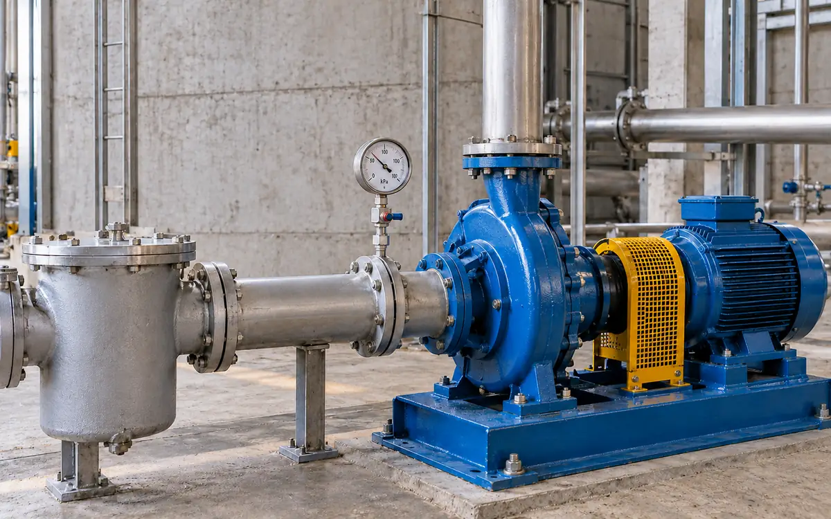
Diagnose the suction condition before replacing the pump
A pump that sounds rough may be drawing air, suffering cavitation or developing a mechanical fault. The sound alone cannot tell the maintenance team which problem to solve.
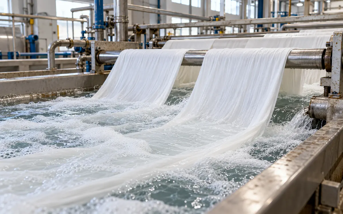
In a textile plant, the fault may appear only when a hot-water tank is low. It may start after a strainer becomes dirty or after a speed change. Replacing the pump without checking those conditions can leave the cause in place.
This guide builds a suction-side balance. It then compares the result with the pump's needs. It also separates vapour formation from air entry and shows how to check a repair. The numerical cases are hypothetical. Their margins and fluid properties are teaching inputs. They are not design limits for all pumps.
Understand what cavitation means
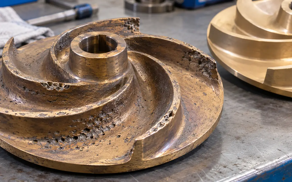
Cavitation begins when local liquid pressure falls below the liquid's vapour pressure. Vapour cavities form. They can then collapse as they reach a region of higher pressure.
Grundfos describes cavitation as the formation and abrupt collapse of vapour-filled bubbles. It can damage a pump and affect its performance.
The key word is local. Pressure at a gauge outside the pump is not the lowest pressure inside the impeller passage. The liquid loses some pressure as it accelerates and turns into the impeller.
A pump may therefore need a pressure allowance above vapour pressure at its inlet. Net positive suction head, or NPSH, expresses the suction condition in metres of the pumped liquid. It provides a way to compare the system's available condition with the pump's stated need.
Keep the investigation tied to the operating state. Temperature, flow, speed and tank level can all change while the same pump remains installed.
Separate available NPSH from required NPSH
NPSH available, NPSHA, comes from the system. It depends on inlet pressure, liquid temperature, level and suction losses. It is not a fixed property of the pump.
NPSH required, NPSHR, comes from the pump maker. It applies to a stated duty and performance basis. Obtain the correct curve for the case. Check the flow, speed, impeller and liquid conditions.
KSB's NPSH reference explains the system and pump values and the need for a clear reference level. Keep that datum consistent when applying a field pressure reading or a tank-level calculation.
The design comparison also needs an appropriate margin. Merely finding NPSHA slightly above a curve value does not prove acceptable long-term service.
Ask the maker to state what its published curve represents. Some documents show NPSH3, a test criterion linked to a 3% head reduction. Others show NPSHR with a stated performance basis. The label and its definition belong in the assessment, not just the number read from the graph.
Use the current margin basis with older pump records
The Hydraulic Institute's 2024 margin update describes a change in ANSI/HI 9.6.1-2024. The guideline uses maker-supplied NPSHR as the reference for margin. That value must be at least the tested NPSH3 value. It can be higher.
An old curve labelled NPSHR may use NPSH3 as its test basis. Do not silently assume that its label matches a newer supplier's definition. Obtain clarification when comparing a replacement pump with the old one.
NPSH3 does not mark the first possible vapour bubble. It is a performance-drop criterion under a test. Treating it as a universal no-cavitation threshold can understate the needed allowance.
The correct margin depends on the application and operating range. Use the relevant guidance and the maker's supported requirements. Do not take a single margin quoted for another pump and apply it to every hot-water, effluent or process duty in the mill.
Build the tank-to-pump balance
For a large supply vessel with a nearly still free surface, a simple steady model is:
NPSHA = (p_surface,absolute − p_vapour) ÷ (ρ × g) + z_surface − z_datum − h_suction.
Use absolute pressure in pascals, density ρ in kg/m³ and g in m/s². The elevation and head-loss terms are in metres of liquid. Use the same pump datum as the required-NPSH information.
The suction loss includes the entrance, pipe, fittings, valves and strainer between the free surface and the pump. Do not include discharge-pipe losses in this inlet balance.
For an open tank, surface pressure is local atmospheric pressure. For a pressurised or vacuum vessel, use its actual absolute headspace pressure. A vessel's nominal design pressure is not an operating reading.
The elevation term is positive when the free surface is above the datum. It is negative for a suction lift. Write the sign convention on the drawing so a raised pump is not accidentally credited with more inlet head.
Keep gauge and absolute pressure distinct
A gauge reading uses local atmospheric pressure as its reference. Vapour pressure is an absolute pressure. Mixing them can create a large calculation error.
For example, suppose a suction gauge reads −20 kPa and local atmosphere is 100 kPa absolute. The suction pressure is 80 kPa absolute. It is not negative absolute pressure.
Use the actual atmospheric basis where it matters. Altitude and weather can affect it. Do not use 101.325 kPa automatically and then treat a small calculated margin as exact.
Check the instrument range and units. A gauge marked bar, kPa or metres of water needs the correct conversion. One bar equals 100,000 Pa, but the head represented by that pressure depends on liquid density.
Also confirm the reading point. Pressure measured upstream of a dirty strainer is higher than pressure at the pump inlet. Using it without subtracting the remaining loss can make the suction condition look better than it is.
Use the liquid's vapour pressure at its real condition
Vapour pressure changes with temperature and composition. Hot water can have far less pressure allowance before vapour forms than cooler water at the same tank level.
For water, the NIST thermodynamic tables provide a recognised property source. Use the correct temperature and pressure basis. For a process liquor, confirm that pure-water properties are a suitable approximation.
Take temperature at a representative point near the pump supply. A tank average may miss a hotter layer or a short hot return. Pair the temperature with the pressure and level during the fault.
Do not solve a hot-return problem by lowering process temperature without approval. The temperature may serve a valid process or feedwater function. Engineering options need to preserve that function while providing a suitable suction condition.
If fluid composition changes by recipe, include the relevant range. A single property value should not become a permanent plant constant unless the duty supports it.
Calculate an available-head example
Consider a hypothetical open-tank duty. Use the following inputs to illustrate the balance.
Input | Assumed value |
|---|---|
Surface absolute pressure | 100 kPa |
Liquid vapour pressure | 20 kPa |
Liquid density | 980 kg/m³ |
Surface above pump datum | 2.0 m |
Total suction head loss | 1.1 m |
Gravitational acceleration | 9.81 m/s² |
NPSHA = (100,000 − 20,000) ÷ (980 × 9.81) + 2.0 − 1.1.
NPSHA = about 9.22 m.
Suppose the maker supplies NPSHR = 4.0 m for this duty. Assume the responsible designer specifies an additional 1.5 m allowance for this teaching case. The resulting minimum accepted available head is 5.5 m.
The calculated 9.22 m exceeds that example criterion by about 3.72 m. This does not prove that the installed pump has no other fault. It only answers the stated suction-head comparison under the stated conditions.
The 1.5 m allowance is invented for the example. It must not be reused as an industry-wide rule or represented as a value taken from the Hydraulic Institute standard.
Test a higher vapour-pressure case
Now change only the assumed vapour pressure to 70 kPa. Hold density, level and loss constant to isolate the effect of that one input.
NPSHA = (100,000 − 70,000) ÷ (980 × 9.81) + 2.0 − 1.1.
NPSHA = about 4.02 m.
That is below the example's 5.5 m criterion by about 1.48 m. A system that looked comfortable at the lower vapour pressure now fails the stated check.
In real hot-water work, density also changes with temperature. Recalculate the relevant properties together. This simple comparison holds density fixed. It does not describe two real water states at two named temperatures.
This result explains why temperature trends are essential. A pump may run well during cool startup and become noisy after hot returns reach the tank. Replacing bearings can remove a damaged component while leaving the thermal cause unresolved.
Check low level and a dirty suction route
Return to the 20 kPa vapour-pressure case. Suppose the liquid surface falls to 0.5 m above the datum. Also suppose suction loss rises from 1.1 m to 2.2 m.
NPSHA becomes 8.321 + 0.5 − 2.2 = about 6.62 m. It still exceeds the hypothetical 5.5 m criterion, but the spare allowance is much smaller.
If the high vapour pressure, low level and dirty route occur together, available head becomes about 1.42 m. Testing each adverse condition alone would miss that combined case.
Build a set of possible operating cases. Include minimum level, highest temperature, maximum flow and expected strainer condition. Do not combine extremes that cannot occur together. Check the combinations that production can create.
Link the case to an operating record. A trend showing temperature and level together is more useful than two separate monthly maxima from unrelated times.
Cross-check with a suction pressure reading
If a suitable pressure tap is at the pump suction reference location, another form is:
NPSHA = p_suction,absolute ÷ (ρ × g) + v_suction² ÷ (2 × g) − p_vapour ÷ (ρ × g).
Add the necessary elevation correction if the tap and required datum differ. This form uses local total head. It should not also subtract the same upstream losses already reflected in the measured suction pressure.
For a separate hypothetical check, use suction pressure 80 kPa absolute. Set vapour pressure to 20 kPa and density to 980 kg/m³. Let suction velocity be 2 m/s with no datum offset. Pressure head above vapour is about 6.24 m. Velocity head is about 0.204 m. NPSHA is about 6.44 m.
The tank method and pressure method should agree when they describe the same steady state and use sound data. A large difference calls for review of taps, elevations, losses, flow and timing. Do not average the two results without finding the reason.
Distinguish vapour cavitation from air entry
Air can enter through a leak on a suction section below atmospheric pressure. It may also arrive from a tank vortex or a poorly arranged return. Those mechanisms differ from the liquid turning to vapour because pressure falls too low.
The symptoms can overlap: noise, unstable flow and reduced head. More than one mechanism may exist at once. A favourable NPSHA result therefore does not rule out every inlet problem.
Observation | Evidence to seek |
|---|---|
Fault begins as liquid gets hotter | Vapour-pressure change and matched suction data. |
Fault begins at low tank level | Available head, intake submergence and vortex behaviour. |
Fault follows strainer loading | Pressure loss across the strainer at the same flow. |
Air is visible in a suitable observation point | Source of entrained gas and return-pipe arrangement. |
Fault persists across sound hydraulic conditions | Mechanical inspection and other process causes. |
Use approved inspection methods. Do not open a live hot suction connection to look for bubbles. Check isolation and stored energy before maintenance work.
Treat intake submergence as its own requirement
The water depth above an intake affects both available head and vortex formation. A system can meet an NPSH calculation and still draw an air-core vortex into the suction route.
The Hydraulic Institute's submergence guidance identifies the need to prevent strong air-core vortices. Intake shape, flow and layout matter in addition to the vertical water depth.
Record the minimum operating level and the intake geometry. Inspect the position of nearby walls, returns and other pump intakes. A return jet can disturb the flow even when the nominal tank level is unchanged.
Do not select a universal minimum depth from an unrelated installation. Use the relevant intake-design method and seek a specialist review for difficult geometry. A model or a more detailed study may be needed for complex cases.
If a level alarm is used, place its setpoint on a valid design basis. Also check its response time. The pump can continue drawing down the tank between alarm detection and the action that stops or changes the duty.
Review flow and speed as part of the cause
Suction losses usually rise as flow rises. The pump's required NPSH also changes with its duty. A new branch or higher speed can therefore reduce the margin from both sides.
The DOE variable-speed pumping guide discusses the effect of speed on suction performance. A speed increase needs a fresh suction review, not just a motor-power check.
If a drive change preceded the fault, retrieve the old and new speed records. Confirm actual flow and the correct curve. Do not assume that a maximum frequency allowed by the drive is acceptable for the pump system.
A lower approved flow or speed may improve the condition, but it must still meet process needs and pump minimum limits. Have the competent engineer assess the change. A temporary reduction in delivery is not a complete repair if production needs the original duty.
Compare remedies against the actual head shortfall
Several changes can increase available head. They include reducing suction loss, lowering the pump relative to the liquid surface, or maintaining a higher valid tank level. Some duties may justify another pump with a lower supported requirement.
Use the balance to compare them. In the higher-vapour-pressure example, NPSHA is 4.02 m. Raising the liquid surface by 2 m would make it 6.02 m if all other terms stayed the same.
That clears the invented 5.5 m criterion by only about 0.52 m. The designer must still review variation and uncertainty. The arithmetic does not prove that the tank can be raised or that its structure and controls are suitable.
Removing 0.5 m of suction loss adds 0.5 m of available head under the same duty. Adding 20 kPa of vessel pressure would add about 2.08 m for the assumed density, but pressurising an open tank is a major design change. It must never be treated as a simple field adjustment.
Avoid fixes that hide or move the fault
Do not throttle the suction valve to quiet the pump. That adds inlet loss and can worsen the available-head condition. Do not remove a required strainer without assessing what then reaches the pump or process.
Do not keep changing bearings while ignoring a repeated hydraulic cause. Use ApparelDiary's bearing failure guide to assess the parts. Check the suction system as well.
A larger motor does not create more available suction head. A larger pump can increase flow and make the inlet problem worse. Match any replacement to the complete duty and inlet envelope.
Keep vibration and noise limits within the equipment's approved operating procedure. Severe or worsening symptoms need the site's defined response. An audit should not require the pump to remain in a damaging state just to collect more data.
Prepare a focused field record
Record pump identity, impeller, speed and curve revision. Add the fluid and property basis, tank level, temperature, surface pressure and suction pressure. Include flow and the state of relevant valves and strainers.
Use one time stamp for each set. Note whether the reading occurred during startup, steady transfer, a level change or a hot return. Retain short trends where the fault is intermittent.
Draw the elevations and reference datum. Mark the pressure and temperature points. A photograph can support the record, but it does not replace a measured level or a labelled pressure basis.
State uncertainty where it could change the decision. A small spare margin supported by rough level estimates and an old gauge is weak evidence. Improve the measurement before treating the result as a confirmed design pass.
Resolve a result that sits close to the limit
The proposed level increase left only about 0.52 m above the example criterion. That small remainder deserves a closer look at the inputs. It should not be rounded into a comfortable pass.
Suppose, only for illustration, that the pressure difference used in the balance could be 2 kPa lower than estimated. With density 980 kg/m³, that reduces available head by about 0.208 m. A liquid level 0.10 m lower removes another 0.10 m. An underestimated suction loss of 0.20 m removes a further 0.20 m.
Those three adverse changes total about 0.508 m. They would nearly consume the spare 0.52 m. This is a deterministic sensitivity check, not a statistical uncertainty calculation or a new margin rule.
Ask which allowances the approved design already includes. Count each source of variation once. Do not assume that the maker's pump requirement covers errors in site data. State how the review handles changes in level and temperature. Include the accuracy of each instrument.
If the conclusion depends on a small difference, improve the weakest input or choose a more robust design. A measured pressure trend may resolve an uncertain loss estimate. A better level record may show that the proposed operating minimum is not maintained. The next test should address that specific doubt.
Verify the correction under the difficult condition
Repeat the operating case that caused the fault. If the problem appeared at hot, low-level duty, a quiet cool-water test is not enough.
Confirm the revised NPSHA comparison and the maker's required basis. Check the same flow and speed, or document an approved change in service. Verify pressure, head and delivery as well as noise.
Inspect damaged parts as needed. Correcting the inlet condition does not restore an eroded impeller or a damaged seal. Repair and hydraulic correction may both be necessary.
Track the result over relevant production cycles. Include strainer loading and tank-level changes where they matter. Put the revised limits and checks in the maintenance programme so the same cause does not return after staff or recipe changes.
Frequently asked questions
Does a positive suction gauge reading rule out cavitation?
No. The liquid may be hot, and pressure falls further inside the pump. Convert the reading to absolute pressure. Account for vapour pressure. Then compare available NPSH with the supported requirement and margin.
Is NPSHR always the same as NPSH3?
No. Check the maker's definition. Current Hydraulic Institute margin guidance uses published NPSHR, which may exceed tested NPSH3. Older records need careful interpretation before comparison.
Can cavitation occur only on suction lift?
No. A flooded inlet can still have inadequate margin because of high vapour pressure, pressure loss, flow or pump requirements. Calculate the actual case instead of judging by the pump's position alone.
Does a quiet pump prove the problem is solved?
Quiet operation is useful evidence, but it is not the whole acceptance test. Confirm the hydraulic margin, required delivery and relevant condition trends. Inspect and repair any existing damage.
Close the fault with a complete suction balance
A useful cavitation investigation connects the symptom to pressure, temperature, level and flow. It uses absolute pressure, a clear datum and the correct maker curve. It also checks air entry and intake geometry.
Choose the remedy from that evidence and test it under the difficult duty. The mill then gains a durable correction, rather than another pump replacement that leaves the same inlet conditions in place.
References
Grundfos: What Is Cavitation?.
KSB: Net Positive Suction Head.
Hydraulic Institute: 2024 Updates to ANSI/HI 9.6.1.
NIST: Water and Steam Thermodynamic Properties.
Hydraulic Institute: Submergence in Pump Systems.
DOE, Hydraulic Institute and Europump: Variable Speed Pumping.

Discussion0
Loading the discussion…