
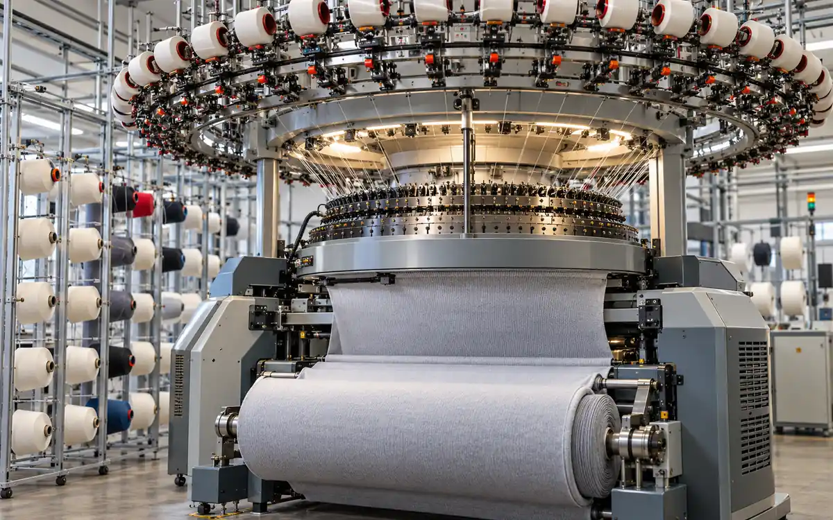
A circular knitting machine can run smoothly while making fabric that fails inspection. One feed may deliver a slightly different yarn length. A damaged needle may leave a persistent line. A restart can mark the tube. The machine's speed display does not reveal all of these problems.
Consider a hypothetical mill trial. A light band appears at a repeating course interval. The first response is to change every stitch cam. First identify the affected feed. Compare its yarn delivery with the approved value. That preserves the evidence and limits unnecessary changes.
This guide explains the machine controls behind that approach. It covers cams, needles, feeders, take-down, measuring devices, and fault isolation. It also develops a plain-jersey output calculation. The numerical examples are original planning examples, not promises for any named model.
Read the machine from yarn package to fabric roll
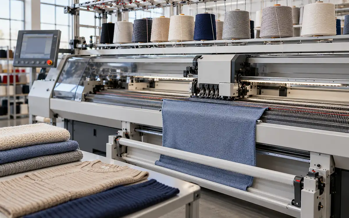
A common large-diameter circular machine draws yarn from a creel. The yarn passes through guides, stop devices, and feeders. The yarn reaches the knitting elements around the cylinder. Fabric then moves through the take-down and winding arrangement.
Cylinder grooves hold the needles. In a common layout, the cylinder rotates. Needle butts follow the cam tracks as it turns. The tracks control the needle's rise and fall. Sinkers support loop formation and fabric control on relevant machine designs. CottonWorks describes these components.
This physical route is also a fault-tracing route. Give each feed a stable number. Carry that number through the creel position, feeder, yarn guide, and trial record. Use the maker's numbering direction so the log agrees with the machine.
Record the actual machine configuration. A product-family name alone may omit key details. Check the fitted gauge, cylinder, feeder arrangement, and control options. Those details affect what the machine can produce.
Cam tracks are not the same as feed count
A cam track provides a route for the needles that engage it. Engagement depends on the needle-butt position or selection arrangement. Feed count describes the number of yarn-feeding knitting stations. The two numbers answer different questions.
For example, Mayer & Cie's Relanit 3.2 HS II page describes up to four needle tracks. It lists 96 feeders for the 30-inch version. These are separate specifications on the same machine. The official product page also gives gauge and speed information.
Do not describe a four-track machine as having only four feeds. Likewise, a large feed count does not establish the pattern range. Ask which needle actions and structures the installed arrangement supports.
Needle technology needs its own check
Latch needles are common in circular knitting. They are not the only type used. Groz-Beckert also documents compound-needle technology for circular knitting.
In that design, a separate closer opens and closes the hook. Its movement follows a separate cam track. The compound-needle technical sheet explains the arrangement.
The maintenance plan must match the fitted system. Check the full part code, machine application, and approved variant before replacement. A general statement about “the needle” can hide a significant difference in mechanism.
Choose the feeder for the demand pattern
The feeder controls yarn supply between the package and knitting zone. Its correct use depends on whether yarn demand is steady, variable, or elastic.
A feeder should be assessed as part of its yarn path. Even a suitable unit can perform poorly. Check for dirt, wrong threading, or an unsuitable setting. Check the actual route before assuming that a different feeder is needed.
Positive feeding
A positive-feeding arrangement meters yarn through a driven feeding element. The setting must suit the intended yarn consumption and machine operation. Measure the resulting delivery rather than relying only on a dial position.
Memminger-Iro's MPF P is a named positive feeder. Its product page lists an interchangeable feed wheel and a knot catcher. It also lists yarn-break stop motion. An outlet feature aims to reduce filament build-up. It also gives a yarn-tension range for that unit. The MPF P specification describes one product, not a universal setting.
For a trial, note the feeder version and feed-wheel arrangement. Record the yarn path and the measured metres per machine revolution. That allows another operator to reproduce the material input.
Do not use a broad instruction such as “turn the quality pulley up to increase GSM.” The direction and effect depend on the drive arrangement and current process. Confirm delivery and measure the fabric after the agreed relaxation or finishing route.
Storage feeding
A storage feeder holds a yarn reserve. It supplies yarn as the process demands it. Its control problem differs from simply assigning a fixed length to every machine revolution.
Memminger-Iro describes the KNITSTORE K52 for both regular and irregular yarn consumption. It monitors stored yarn quantity and provides yarn-consumption measurement through its operating terminal. The K52 page also states the available operating ranges.
For a pattern with variable demand, review the full repeat. An average delivery figure may hide a short demand peak. Check whether a stop or tension change always occurs at the same pattern section.
Elastane feeding
Keep the elastane path separate in the setup record. State the material, package, feeder, delivery condition, and measurement method. Do not assume that the ground-yarn setting defines elastane delivery.
The MER 4 is an elastane roller. It provides positive feeding of plain elastane to large-diameter circular machines. The maker lists several sensor-unit versions. The official MER 4 page identifies that application.
The feeder's purpose alone does not establish the finished elastane percentage. Nor does it establish stretch recovery. Those results depend on the actual material input and the subsequent process. Verify them using the relevant product measurements.
Separate yarn length, yarn tension, and fabric mass
These three quantities often get treated as one control. They are different.
Yarn length describes how much material reaches the knitting system. Yarn tension describes force in the yarn path. Fabric mass per area combines yarn mass with the area occupied by the fabric in a stated condition.
A tension value cannot replace a yarn-length measurement. Nor does one mass-per-area result prove that every feeder is balanced. Several local differences could exist in a fabric whose average mass is on target.
Memminger-Iro's MLT WESCO sheet illustrates the distinction. It lists yarn consumption, yarn speed, and machine speed as separate readings. Tension readings include normal, average, and peak values. It reports consumption in length per machine revolution. The official meter factsheet shows the measurement categories.
Use an instrument and procedure suitable for the running yarn. Confirm its setup and calibration status. Follow the approved safe method for placing it in the yarn path. Do not improvise an unsafe reach to obtain a reading.
Worked example: infer average loop length
Assume a plain-jersey trial has 2,640 active needles. One feed forms one loop on each active needle per revolution. A suitable measurement records 79.2 m of yarn over ten machine revolutions at that feed.
Yarn per revolution = 79.2 m / 10 = 7.92 m/rev
Average loop length = 7.92 m / 2,640 loops = 0.003 m/loop
Average loop length = 0.003 × 1,000 = 3.00 mm/loop
This estimate assumes all measured yarn enters those loops. A pattern with misses, tucks, or extra yarn paths needs a different calculation. Check for other consumption differences too.
Now suppose another feed records 80.0 m over the same ten revolutions:
Second average loop length = 80.0 / 10 / 2,640 × 1,000 = 3.0303 mm
Delivery difference = (80.0 - 79.2) / 79.2 × 100 = 1.01%
The difference is a reason to investigate. It is not automatically a defect or a universal failure limit. The approved product tolerance, measurement variation, and visible fabric result decide its significance.
Repeat the reading under the same conditions. If it remains different, inspect that yarn path and feeder setup. Do not use a single reading to justify changing the whole machine.
Gauge, diameter, and actual needle count
Machine gauge expresses needle positions per inch around the relevant needle bed. Diameter describes cylinder size. Both affect the approximate number of needle positions.
For an ideal circular geometry:
Approximate needle count N = π × diameter D (inches) × gauge E (needles/inch)
For a hypothetical 30-inch, E28 cylinder:
N = π × 30 × 28 = 2,638.94 needle positions
Needles come in whole numbers. The actual cylinder must also meet its design and pattern requirements. Use the maker's installed count for production calculations. Do not round this estimate and treat it as a spare-part specification.
The examples in this guide use a stated actual count of 2,640. That count is an assumption for the calculation, not a claim about every 30-inch E28 cylinder.
Do not confuse cylinder circumference with finished open width. The fabric's width changes with structure, loop length, relaxation, and finishing. Measure width at the same process state used for the mass or output calculation.
Calculate output with visible assumptions
A common plain-jersey calculation starts with loops formed per minute. It becomes useful only when the active-needle and active-feed assumptions are clear.
For this hypothetical case, assume:
Input | Value | Meaning |
Active needles | 2,640 | Each forms one loop at every active feed |
Active feeds | 96 | All knit the stated plain structure |
Machine speed | 25 rpm | Steady running speed |
Average loop length | 3.00 mm | Ground yarn only |
Yarn linear density | 20 tex | 20 g per 1,000 m |
Scheduled shift | 8 h | Defined planning window |
Running fraction | 85% | Includes recorded machine stops |
Accepted mass fraction | 97% | After stated quality checks |
First calculate loop formation:
Loops/min = active needles × active feeds × rpm
Loops/min = 2,640 × 96 × 25 = 6,336,000
Convert loop length to metres before multiplying:
Yarn length/min = 6,336,000 × 0.003 m = 19,008 m/min
Use tex to convert yarn length into mass:
Yarn mass/min = 19,008 × 20 / 1,000 = 380.16 g/min
Then convert grams per minute into kilograms per hour:
Gross mass rate = 380.16 × 60 / 1,000 = 22.8096 kg/h
Apply the running and acceptance fractions once:
Accepted shift mass = 22.8096 × 8 × 0.85 × 0.97 = 150.45 kg
This is a simplified ground-yarn balance. It excludes yarn discarded before it enters the fabric and any added elastane or other yarn. It also assumes the stated loop length and yarn count remain representative.
Use it to check an observed result. Do not treat it as a substitute for weighing accepted rolls.
Cross-check length and area
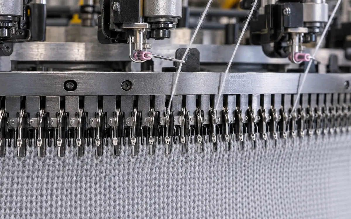
In the same plain structure, each active feed produces one course per revolution.
Courses/min = 96 × 25 = 2,400
Assume a measured density of 16 courses per centimetre at the selected process state.
Course density = 16 × 100 = 1,600 courses/m
Fabric length rate = 2,400 / 1,600 = 1.50 m/min
At 60 running minutes, that is 90 m. Assume the fabric's measured equivalent open width is 2.00 m in the same condition.
Area per running hour = 90 m × 2.00 m = 180 m²
Calculated mass per area = 22.8096 kg × 1,000 / 180 m² = 126.72 g/m²
The length, width, density, and mass must refer to the same material state. Using relaxed width with stretched take-down length would mix incompatible measurements.
For a tube, be clear whether the recorded width is laid-flat width or equivalent open width. Confusing them can create an error of about a factor of two in an area calculation.
Understand the speed factor
Mayer & Cie lists a speed factor of 1,500 for the named Relanit model, expressed as 50 rpm at 30 inches. This follows the product of diameter in inches and rpm. The specification gives the stated limit for that configuration.
A speed factor is a machine-comparison convention. It is not kilograms per hour. Useful output still depends on yarn, pattern, and active feeds. Quality requirements and actual running time also matter.
The hypothetical example above uses 25 rpm. It does not assume that the catalogue's maximum speed is suitable for the trial yarn.
A faster trial can deliver less accepted fabric
Suppose a second hypothetical trial raises speed from 25 to 28 rpm. Keep the same needle count, active feeds, yarn count, and loop length. The theoretical running mass rate rises in direct proportion to speed:
Faster running rate = 22.8096 × 28 / 25 = 25.546752 kg/h
Now assume this trial runs for only 70% of the eight-hour shift. Its accepted mass fraction is 94%. These trial observations are invented for the example. Increasing speed does not necessarily produce these effects.
Faster-trial accepted mass = 25.546752 × 8 × 0.70 × 0.94 = 134.48 kg
The earlier setting delivered a calculated 150.45 kg. The faster trial therefore gives about 15.97 kg less accepted fabric over the same shift.
The result does not prove that 25 rpm is best. It shows which evidence is missing from a speed-only comparison. Investigate why running time and acceptance fell. The cause may be repair time, yarn supply, setup, or a change elsewhere in the trial.
Repeat a fair comparison before releasing the setting. Keep the yarn, pattern, staffing, and inspection rule comparable. Separate deliberate test stops from normal production stops. State how each is counted. A detailed inspection trial may involve more planned stops. Those stops alone could make it appear less productive.
Isolate faults with two coordinates
Give every defect a position across the fabric. Also record when it occurred during production. Then connect those coordinates with the machine record.
A lengthwise mark deserves a check of the corresponding knitting elements and fabric path. A course-related band deserves a check of feeds, yarn identity, and delivery. A restart mark deserves a check of the stop and restart event.
These are starting hypotheses. They are not proof of a cause.
A controlled feeder comparison
Return to the hypothetical light band from the introduction. Mark the sample's course direction and identify the repeating interval. Review the feed and yarn map for that part of the structure.
Compare yarn identity first. If two feeds use different lots, correcting delivery alone may leave a visual difference. Then compare measured yarn length and tension under matched conditions.
If a permitted swap test is useful, change one identified item and document it. For example, move a known yarn package according to the approved trial plan. Observe whether the defect follows the package or stays with the feed position.
Do not swap several packages and feeders at once. The resulting fabric may improve, but the cause will remain uncertain. Restore the approved arrangement unless the trial formally releases a change.
Use a fault table as a decision aid
Observation | Record immediately | Next evidence to seek |
Persistent lengthwise line | Fabric position and needle reference | Part condition and repeatability |
Repeating course band | Repeat interval and feed map | Yarn identity and measured delivery |
Random holes | Time, position, and stop history | Yarn breaks, component damage, or handling event |
Restart mark | Stop duration and restart sequence | Delivery and take-down response |
Oil mark | Location and recent maintenance | Leak source and lubricant application |
Mass drift | Sample condition and measurement method | Count, loop length, width, and density changes |
A table cannot replace a technician's judgement. Its purpose is to stop the team from losing useful evidence before the first adjustment.
Keep rejected samples with their roll and time references. A defect found after dyeing may need to be traced back to knitting. A sample with no identity rarely supports that investigation.
Approve a machine setting through a complete trial
A trial should include the expected production conditions. Use the intended yarn lot, feeder arrangement, structure, and finishing route. Confirm the basic machine condition before comparing settings.
Start with a written acceptance plan. Include fabric appearance, width, mass, dimensional behaviour, and the product's relevant performance requirements. Set the sampling locations and measurement state in advance.
ApparelDiary's yarn-selection trial guide provides a useful starting point for the material record. Carry that yarn identity into the machine trial.
Check starts as well as steady running
Observe the first approved start. Also check the restart conditions that matter to the order. Record the resulting fabric length that needs segregation. Do not report only the clean middle of the roll.
For example, a faster setting may create more stop-related waste. Compare accepted mass over the full observation window. A higher steady rate can lose its advantage. Frequent stops or slow recovery can cancel the gain.
Retain the actual stop durations. Twenty short stops may take as long as two major repairs. The two cases need different improvements.
Repeat the accepted setup
After identifying a suitable setting, reproduce it. Use the saved record rather than the operator's memory. Check whether another shift can obtain the same measured delivery and fabric result.
Save the machine configuration and programme or cam arrangement in the release record. Add yarn identities, feeder setup, take-down settings, and the approved sample. Add the measured values and the conditions under which they were taken.
Record the allowed changes. If an operator may adjust a setting within a proven range, state that range and the required check. If a change needs technical approval, make that responsibility clear.
Maintain the system that produced the sample
Preventive work should support a specific production result. Keep yarn paths clean and inspect wear. Maintain the approved lubrication system. Verify stop functions using the maker's procedure.
Treat repeat replacement as a signal. If the same needle position repeatedly fails, look for a related cause. Replacing the needle each time may leave the cause unresolved. The resulting waste then becomes routine.
Keep cleaning tools and materials compatible with the installed parts. Avoid a general solvent or compressed-air instruction copied from another machine. Follow the maker's method and the site's safe-work rules.
ISO 11111-6 addresses fabric-manufacturing machinery, including knitting, together with Part 1. The published 2005 edition has amendments from 2009 and 2016. A revision is under development. The official scope and status page identifies the relevant family.
The public scope does not provide a complete maintenance or guarding procedure. Use the applicable full requirements and the machine's instructions. Isolate the required energy sources before intervention. Never defeat a guard to observe the knitting action.
Questions worth asking during a machine comparison
Are more feeders always better?
More active feeds can increase course output in a suitable plain structure. That does not mean every pattern can use every feed in the same way. Compare the intended fabric and the actual arrangement.
Can a correct GSM hide an uneven setup?
Yes. An average mass-per-area result can be acceptable while individual feeds differ. Combine the fabric measurement with local delivery checks and visual inspection.
Can a higher speed compensate for poor yield?
It may raise gross output while leaving accepted output unchanged or lower. Compare accepted mass over equal time windows and include the waste associated with stops.
What should an operator record after a change?
Record the changed setting, its previous value, the reason, and the affected sample or roll. Add the measured result. A note saying “quality improved” is too vague to reproduce.
Turn machine settings into evidence
A stable circular-knitting process needs more than a list of components. It needs a clear relationship between the feed settings, the loops formed, and the fabric that passes inspection.
Measure yarn delivery with explicit units. Use the actual needle and active-feed counts. Trace faults before making broad changes. When a setting works, preserve the machine record and the finished sample together. The next order can then begin with evidence instead of guesswork.
Knitting faults often trace back to yarn, so see selecting yarn for knitting, yarn package winding, yarn twist and yarn clearing.
Discussion0
Loading the discussion…