
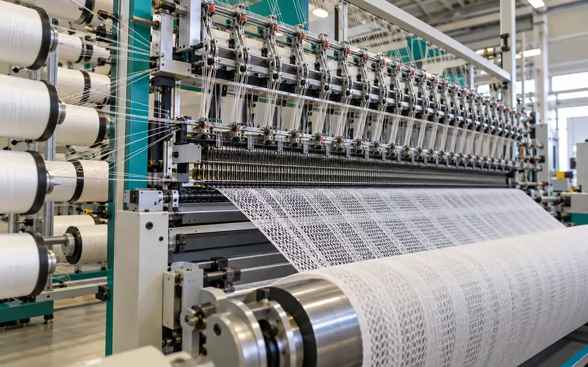
A narrow line appears in a roll of warp-knit fabric. Before changing the pattern, the technician needs to know its width position and when it began. The cause might lie in a knitting element, a threaded end, or the yarn supply. The fabric is the evidence that links those possibilities to a specific part of the machine.
Warp knitting depends on coordinated motion across the working width. Needles form loops while guides place yarn. Let-off supplies the yarn, and take-up draws the fabric away. A useful setup record shows how those motions and material flows work together.
This guide follows the machine from beam to fabric roll. It explains guide-bar motion, separates pattern control from yarn delivery, and shows how to calculate run-in, output, and yarn mass. The worked examples are hypothetical. They are tools for process planning, not operating recipes.
Understand the machine as a coordinated system
In warp knitting, needles move together on needle bars. Yarn generally arrives from warp beams or creels. Machine designs differ in the arrangement of knitting elements and yarn supplies. Groz-Beckert's warp-knitting overview describes this shared principle across a wide range of applications.
A needle bar is not a guide bar. The needle bar carries the elements that form and hold loops. A guide bar carries guides that present yarn to those needles. Confusing the two makes fault reports and setup instructions unclear.
The fabric take-up draws the formed fabric away from the knitting zone. The batching unit winds it into a roll. These functions may use separate drives. The warp let-off supplies yarn from the beam side.
For a named example, Karl Mayer's TM 2 factsheet lists electronic yarn let-off, an electronic four-roller fabric take-up, and a separate batching device. It also lists a pattern-disc arrangement. Thus, electronic material control does not imply that every motion on the machine uses electronic pattern control. The TM 2 factsheet makes those distinctions visible.
Tricot and Raschel are starting labels
Machine family names help identify the general production route. They are not enough to specify the required product capability.
Karl Mayer offers tricot machines with two, three, or four guide bars. Its range includes machines for stretch and non-stretch fabrics. The choice depends on fabric construction and end use. The official tricot range is a better starting point than assuming that all tricot machines have two bars.
For procurement, define the intended fabric first. List yarn types, structure, working width, guide-bar functions, and the required finished properties. Then compare the machine configurations that can make that fabric.
Do not assume that extra bars will be useful on every order. They add possibilities only when the product and yarn supply need them. A simple repeat can be commercially sound on a simpler machine.
What the main knitting elements do
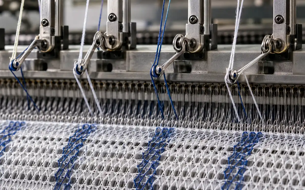
A compound needle has a hook member and a separate closing element. Their relative motion opens and closes the hook during the cycle. Sinkers help control the fabric and provide the required support during loop formation. The exact shape and motion depend on the machine.
The Textiles Committee training module describes these elements and their roles. It also distinguishes guide-bar swinging from sideways shogging. Its warp-knitting module provides a useful basic description, but a technician must use the installed machine's manual for settings.
Think of the knitting zone as a set of matched parts. Needle, closer, guide, and sinker positions must remain compatible. A replacement chosen only by its rough appearance may fail to fit that relationship.
Groz-Beckert's compound-needle sheet shows model-specific hook, shank, and mounting options. It also identifies special wear-protection variants. The manufacturer's component sheet supports ordering by the full approved designation.
Keep spare parts in labelled packs. Record the machine, gauge, part code, variant, and installation location. If a fault appears after a repair, that record lets the team check what changed.
Inspect the complete path of one end
Choose a yarn end that corresponds to a visible fault. Trace it back from its guide through the yarn path to the correct supply. Check identity and route before changing tension.
On the fault sample, mark the face and direction of travel before it leaves the machine. Record the fabric position, guide position, guide-bar label, and beam or creel supply. A sample turned over without those marks can send the next technician to the wrong side.
Keep the marked sample with the yarn-path record during shift handover. Add the last accepted sample and the first affected length if they are available. The next operator can then continue the investigation from a known point.
Swinging, shogging, overlap, and underlap
Guide bars combine two basic motions. Swinging takes guides through the spaces between needles. Shogging moves them sideways, along the needle bar.
An overlap is the yarn placement on the hook side of the needles. An underlap is the connection formed on the other side between successive overlaps. The movement must occur at the correct part of the cycle, with the guides clear where required. The INFLIBNET teaching chapter explains these motions and their relationship to the yarn path.
The terms describe the yarn's path around the knitting elements. They should not be reduced to “front movement” and “back movement” without stating the machine view. A drawing viewed from the other side can reverse what a reader calls left and right.
Read a lapping record with its legend
Before using a lapping diagram or numerical notation, establish four things:
Which side of the machine the drawing shows.
How needle spaces and guide bars are numbered.
Which movement belongs to the overlap.
Where the repeat begins and ends.
Then trace one yarn through a complete repeat. Check that the final position joins correctly to the next repeat. Do this before comparing the notation with a machine file.
A training drawing should include an arrow for the viewing direction. It should also identify the yarn path of each bar. A bare sequence of numbers copied into a worksheet is weak evidence because the convention may be missing.
For example, two engineers may draw the same path from opposite sides. Their sketches can appear reversed while describing the same physical motion. The remedy is to agree the view and numbering, then compare the complete path.
Do not use an outdated standard label as proof
ISO 10223:2005 dealt with guide-bar designation and numbering. ISO now lists it as withdrawn, with withdrawal recorded on June 25, 2025. The official status page should be checked before an old specification calls it current.
A factory still needs clear bar labels. Use the installed machine's documentation and record the convention in the setup sheet. If a contract invokes an older document, identify the edition and resolve that requirement with the parties responsible.
Withdrawal does not erase the numbering used on an existing machine. It means that the old document should not be presented as a current ISO standard.
Separate pattern drive from yarn-feed control
The pattern drive determines guide-bar shogging. A mechanical system may use discs or chains. Electronic systems use controlled drives and a stored movement sequence.
Karl Mayer describes the development of its EL electronic guide-bar control and its later use in other machine functions. The same account describes Advanced Feeding Control for patterns with changing yarn demand. The manufacturer's technical history shows the link between pattern motion and feed control.
That link does not make the two settings interchangeable. A correct movement sequence still needs the right yarn supply. A feed change does not correct a wrong overlap.
A practical setup record should therefore hold separate entries for:
Lapping or pattern file and revision.
Threading plan for each bar.
Run-in or yarn-delivery setting for each supply.
Fabric take-up setting.
Approved speed and start-stop conditions.
Inspection and finished-fabric acceptance points.
This separation is useful during a changeover. If the structure changes while the old run-in values remain, the file name alone will not show the mistake.
Compare demand over the repeat
An average run-in value describes total yarn used over a stated number of courses. It does not show every short-term change in demand within a complex repeat.
When a problem occurs at the same part of each repeat, inspect that section of the motion and feed record. Do not assume that a correct overall average proves stable delivery at every instant.
Electronic control can help manage such changes, but its presence is not a guarantee. Confirm the available function on the specific machine and prove it with the intended yarn and pattern.
Run-in: state the denominator before calculating
Run-in expresses yarn delivered per end over a defined amount of knitting. Units must be explicit. A value written as “4.8” is incomplete.
For the following original example, use metres of yarn per end per 1,000 courses. This avoids relying on an unstated rack convention. If a factory uses racks, write the course count per rack on the same sheet before converting.
Assume two guide-bar supplies:
Quantity | Supply A | Supply B |
Active yarn ends | 2,000 | 2,000 |
Yarn linear density | 5 tex | 7.5 tex |
Run-in per end per 1,000 courses | 4.8 m | 6.4 m |
Trial knitting rate | 1,800 courses/min | 1,800 courses/min |
The table describes a hypothetical repeat and material balance. It is not the specification of the TM 2 or any other named machine.
Yarn delivery per end follows directly from the units:
Delivery (m/min per end) = run-in (m per 1,000 courses) × courses/min / 1,000
For supply A:
Delivery A = 4.8 × 1,800 / 1,000 = 8.64 m/min per end
For supply B:
Delivery B = 6.4 × 1,800 / 1,000 = 11.52 m/min per end
The two supplies do not consume equal lengths. Equal starting lengths would therefore not produce equal running times.
Suppose each end on supply B has 30,000 m of usable yarn remaining. Assume the stated delivery remains steady while running.
Remaining running time = 30,000 m / 11.52 m/min = 2,604.17 min
Remaining running hours = 2,604.17 / 60 = 43.40 h
This is running time. Stops extend elapsed clock time. Tail allowances, unusable remnants, and uncertainty in the length estimate must be handled separately.
The result helps plan a beam change. It does not authorize an unattended run.
Calculate fabric output from courses and density
Machine speed and fabric speed are different quantities. The relationship needs the course density at the point where fabric length is measured.
Continue the hypothetical example. Assume that one machine cycle produces one course at 1,800 courses per minute. Measured take-up density is 18 courses per centimetre.
Course density = 18 courses/cm × 100 cm/m = 1,800 courses/m
Fabric speed = 1,800 courses/min / 1,800 courses/m = 1.00 m/min
A shift has 480 scheduled minutes. Assume actual running occupies 86% of that time.
Running minutes = 480 × 0.86 = 412.8 min
Gross fabric length = 1.00 × 412.8 = 412.8 m
If 95% of that length meets the defined acceptance requirement:
Accepted length = 412.8 × 0.95 = 392.16 m
State where that length is measured. A take-up metre is not automatically a finished, relaxed metre. If the customer buys finished length, measure the conversion through the actual finishing route.
Also state whether the running-time factor already includes stops. Do not deduct those same stops again under another efficiency heading.
Check mass against yarn delivery
Tex means grams per 1,000 metres. ApparelDiary's yarn-count conversion guide explains this unit and related systems.
For 1,000 courses, supply A uses:
Yarn length A = 2,000 ends × 4.8 m/end = 9,600 m
Yarn mass A = 9,600 m × 5 g/1,000 m = 48 g
Supply B uses:
Yarn length B = 2,000 × 6.4 = 12,800 m
Yarn mass B = 12,800 × 7.5 / 1,000 = 96 g
The total yarn input is 144 g per 1,000 courses.
At 1,800 courses per metre, those 1,000 courses form 0.5556 m of fabric. Assume a measured take-up width of 2.00 m. Use unrounded values in the calculation.
Fabric area = (1,000 / 1,800) m × 2.00 m = 1.1111 m²
Calculated mass per area = 144 g / (1,000 / 1,800 × 2.00) = 129.6 g/m²
This simplified balance assumes all delivered yarn enters the measured fabric. It excludes waste, added finish, and moisture differences. The width and density refer to the same process state.
If a measured sample differs greatly, check the input units first. Then check active-end counts, run-in, sample area, waste, and conditioning. A mass balance is a diagnostic aid; it does not replace the agreed fabric test.
See how a density change affects both measures
Suppose a second trial has 20 courses per centimetre at take-up. Keep the hypothetical yarn input per 1,000 courses and the 2.00 m width unchanged. The same courses now occupy less area.
New area = (1,000 / 2,000) × 2.00 = 1.00 m²
New calculated mass per area = 144 g / 1.00 m² = 144 g/m²
At the same 1,800 courses per minute, fabric speed becomes:
New fabric speed = 1,800 / 2,000 = 0.90 m/min
The calculated mass per area rises while length output falls. This follows from the stated assumptions; it is not proof that a real adjustment leaves yarn input or width unchanged. Measure both again in the actual trial.
This comparison helps a planner avoid an impossible request: increasing density while promising the same metre output from the same course rate. A revised fabric specification needs a revised capacity check.
A trial that proves more than machine speed
Choose the acceptance fabric from the products the mill expects to make. It should exercise the required bars, yarn supplies, and control functions. A simple demonstration may prove that the machine runs, yet leave the difficult order untested. Identify that gap in the trial agreement.
Define the trial boundary beside the output target. A complete changeover includes beam loading, threading, first-quality approval, and roll removal. A stable running test starts after setup. These measurements answer different planning questions, so keep their results separate.
Before the run
Confirm the machine identity and installed configuration. Match the part codes to the approved setup. Check the pattern revision, threading plan, supply identities, and run-in units.
Review the finished-fabric requirements. Set the checks for width, mass, structure, appearance, and any intended functional property. Record how samples will be finished and conditioned before comparison.
Check the yarn path and stop functions using the maker's approved procedure. Resolve missing ends or unclear guide assignments before speed is raised.
During the run
Record actual running time and stops by cause. Mark the corresponding fabric positions. Keep enough information to distinguish a start mark from a steady-state defect.
Sample across the width. A centre-only sample can miss an edge problem or a difference between supply sections. Include material near the beginning and later in the run to see whether the process changes.
Log each setting change against a fabric marker or recorded length. Write the old value, new value, reason, and sample identity. If several variables change together, mark that limitation in the trial report. A later improvement may then be linked to that group of changes, but not confidently assigned to one setting.
After finishing
Review the fabric at the agreed final state. Groz-Beckert notes that stripes in fine elastic warp knits may become visible only after finishing. Its industry brochure supports including this later check.
Compare the defect positions with the machine log. Keep the start-up portion separate from stable production when assessing the cause, while retaining both in the total yield calculation.
Approve a repeatable setting range only after the evidence supports it. One attractive roll does not establish how the process responds to a new yarn lot or a restart.
Troubleshoot with a location and a time
The quickest useful fault report tells the technician where the defect appears and when it began.
Symptom pattern | Evidence to collect first | Next controlled check |
Persistent lengthwise line | Width position and affected yarn path | Guide, needle, closer, and end identity |
Mark at each restart | Stop duration and restart settings | Approved start sequence and feed response |
Repeat-linked disturbance | Course position within the repeat | Lapping sequence and changing yarn demand |
Width or density drift | Take-up record and measurement state | Drive setting, measurement, and finishing route |
Fault after a repair | Part code and installation position | Correct component variant and approved alignment |
Defect in one supply section | Beam section and threaded-end map | Supply condition and yarn path |
These entries are investigation steps, not automatic diagnoses. Follow the installed machine's instructions for any adjustment.
Return to the narrow line in the opening example. Suppose it stays at the same fabric position through several rolls. Trace that position to the guide and knitting elements, using the marked sample. If the fault instead follows a changed yarn supply, retain that supply identity for the next check. Neither pattern proves the cause, but each directs the investigation.
Choose one justified change under the machine's approved procedure. Mark the trial fabric and repeat the same inspection. If structure, feed, and take-up all change at once, a better roll will not show which adjustment mattered. Preserve the old setup so the comparison remains clear.
For a recurring stop, record repair time as well as frequency. Ten short end repairs and one long mechanical stop may consume similar time but require different improvements.
Maintenance, guarding, and change control
Maintenance should protect timing, alignment, clean yarn paths, and reliable control functions. Use the maker's intervals and procedures for the installed configuration. Add inspections when fault history shows a repeated local problem.
Do not force a guide or needle into alignment by eye. Stop and use the specified method, tools, and competent personnel. A small part in the knitting zone can affect a wide strip of fabric.
ISO 11111-6 covers fabric-manufacturing machinery, including knitting, together with Part 1. The published 2005 edition has amendments from 2009 and 2016. ISO also lists a revision in development. The official scope and status identify the relevant safety-document family; the public abstract is not the full machine-safety specification.
For intervention, follow the required isolation procedure. Use approved safe modes for observation. A stop button alone should not be assumed to provide the isolation needed for maintenance.
Keep an approved setup copy before a change. Record who released the new version and which orders it covers. An unnamed local edit can otherwise appear months later as an unexplained difference between machines.
Questions to settle before ordering a machine
Give the supplier a trial brief that names the intended fabric and yarn. Attach the required configuration to the quotation. It should identify guide-bar functions, yarn-supply control, working width, gauge, take-up, batching, monitoring, and service needs.
Place the unit and production boundary beside each quoted performance figure. Shaft speed and courses per minute describe machine motion. Metres per hour needs a fabric-density basis. Accepted kilograms per shift also depends on running time and yield. Compare offers only after those bases are aligned.
Have the supplier confirm the fitted options in writing. A feature shown for a product family may be absent from the quoted model. Resolve that point before the purchase comparison moves to price.
Does a longer underlap always improve fabric strength?
No single direction of change establishes final performance. Yarn, structure, density, and finishing all contribute. Compare the intended property using matched samples and the agreed test method.
Is electronic patterning enough to solve yarn-feed faults?
No. It controls a movement sequence. Yarn supply, threading, component condition, and the available feed-control functions still need to be correct.
Can an old successful setup be reused unchanged?
Treat it as a starting record. Confirm the yarn lot, machine configuration, file version, and finished acceptance result. Reuse becomes reliable when those conditions are traceable.
Keep motion, material flow, and fabric results connected
The approved setup should connect bar motion, yarn delivery, and the accepted fabric. Keep the lapping convention with the pattern record. Give run-in a stated denominator and measure output at a named fabric state. Retain the inspection result after the agreed finishing route.
Those connections make the next decision easier. A fault can be traced to a location and time. A capacity figure can be checked from its units and assumptions. A repeat order can begin from an approved record whose limits are understood.
Knit quality depends on yarn supply, so see selecting yarn for knitting, yarn package winding, yarn twist and elastane fibre.
Discussion0
Loading the discussion…