
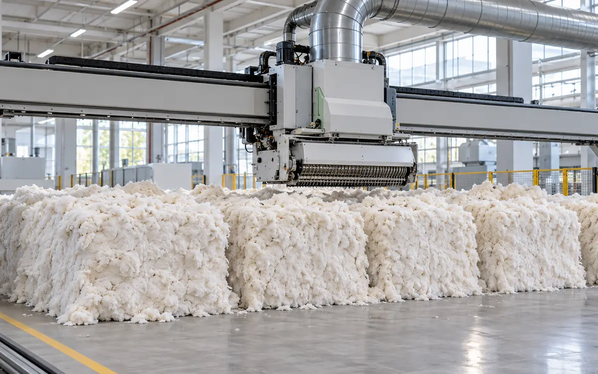
The first machine should deliver a steady fibre supply
An automatic bale opener removes small amounts of fibre from a planned group of bales. Its job is to feed the next stage with a controlled stream of tufts. The quality of that stream matters as much as its mass per hour.
A fast take-off head cannot solve every blowroom problem. A full receiver may stop the line. Unstable transport air can also interrupt flow. The next machine may be unable to accept more fibre. A bale group may also look even while its local density varies. Good operation starts by separating these causes.
This guide explains how automatic bale openers work. It covers their controls, output calculations, and mill trials. It focuses on the machine and its handoff to the blowroom. Cotton selection is a separate task; ApparelDiary's guide to reading an HVI report before choosing a bale mix covers that decision.
How a travelling take-off system works
In a travelling system, the opening head passes over the bale laydown. Its rotating elements remove fibre from the upper surface. Repeated passes work down through the bales. The removed tufts enter the material transport system.
The exact arrangement depends on the model. Rieter's UNIfloc A 12 uses a take-off roller and direct drives. It measures force as it scans the laydown. The machine opens the removed material into small tufts for later processing. These are features of the named machine, not a definition of every bale opener. See the Rieter A 12 product description.
Trützschler's portal BO-P spans a wider laydown. The published design has two opening rolls. Five to seven bales can sit side by side. The head can work across up to fourteen bales at once. This layout affects the space needed. It also changes how the mill presents the bales. See the Trützschler bale-opener range.
The common idea is gradual removal from many bale surfaces. It reduces reliance on large, irregular hand-fed lumps. It does not mean that every fibre has become separate, or that the full cleaning process is complete.
What each main part contributes
Think of the machine as several linked systems. The travelling structure positions the head. The vertical movement controls its relation to the changing bale surface. The opening elements remove fibre. The duct carries the removed tufts away. Sensors and controls coordinate these actions.
System | Main task | Question during a trial |
Travel mechanism | Move through the approved working area | Is travel smooth through the full route? |
Take-off head | Remove fibre in small amounts | Is removal consistent across the bale group? |
Height or profile control | Follow the changing surface | Does the machine handle uneven starting heights? |
Material transport | Carry tufts to the next stage | Does fibre leave without repeated accumulation? |
Line control | Respond to downstream demand | Are stops caused by the opener or the receiver? |
Protective devices | Control access to hazardous motion | Has the installed system been validated? |
This table describes functions to review. Use the supplier's drawings to locate each part. The drawings should also show the protected zones on the installed machine.
Bale height and density are different inputs
A high bale is easy to see. A dense region may be less obvious. Two areas can have the same layer depth but different effective densities. Removing that layer can yield a different mass from each area. That is a basic reason to avoid treating height alone as a complete measure of feed.
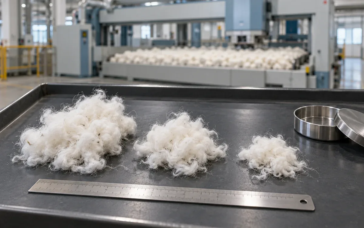
Rieter's VARIOline brochure explains its force-based profiling method. The first run assesses bale height and density. Later passes remove layers based on that profile. The brochure also links small tufts with greater exposed surface for later cleaning. It does not establish a universal tuft-mass target for all materials.
For a mill trial, record the initial bale condition. Note gaps, uneven heights, damaged packaging, and any approved differences in orientation. Take photographs before operation. Then record where abnormal removal occurs. Check where the symptom occurs. Does it follow one bale position, or does it occur at every reversal? Those patterns suggest different causes.
Keep raw-material changes visible in the record. A new fibre type or finish may need a different approved recipe. First explain the material change. Do not try to offset it by changing several machine settings at once.
The machine's ability to handle a laydown also has limits. Ask the supplier to confirm the allowed bale sizes and fibre types. Check any limits on material condition too. Do not assume a staple-fibre opener can handle unprepared textile waste.
Lay out the working area around the actual installation
A brochure's machine length is only one part of the floor-space requirement. Allow space to deliver and unwrap bales. Service access and protected travel need space too. Include the next laydown in the plan. Review those activities on a scaled plan.
Trützschler's blowroom technical data distinguishes machine length from work-off length. It lists different work-off widths too. Gaps between bale groups reduce the length available for opening. Do not simply divide building length by bale length. That calculation can overstate the space available for bales.
Use the supplier's approved layout for the specific configuration. Mark columns, doors, ducts, floor joints, and delivery routes. Check the moving envelope of the head and structure. The empty machine footprint may be smaller than the space needed in operation.
Plan material identification at the same time. The operator needs to match each bale group to its recipe. The intended destination must be clear too. Place labels where they remain readable through normal work. Do not rely on a label that disappears with the bale wrapping.
A larger laydown can provide longer running time, but only if the correct material can be staged and used. It may also tie up more raw material. Compare those practical effects before choosing the longest available track.
Read capacity claims with their conditions attached
Published outputs help narrow a selection. They are not a substitute for a trial with the intended fibre and line.
Published example | Supplier-stated output | What to confirm before using it |
Rieter UNIfloc A 12 | Up to 2,400 kg/h line production | Material, assortment count, configuration, and line basis |
Trützschler BO-P | 2.5–3.0 tonnes/h | Working width, material, and required installation |
Trützschler BO-E | Approximately 750 kg/h | Whether a smaller feed arrangement suits the lot pattern |
The figures come from the current Rieter A 12 page and Trützschler product page. They describe different products and are not a controlled performance comparison.
The Rieter brochure also separates outputs by material and number of assortments. This matters when one opener serves several material groups. Time spent moving between them and serving each route is part of the duty. A single-assortment headline is not automatically available to each of three lines.
Request a written duty point. It should name the material, required output, operating schedule, destinations, and quality limits. Ask where the rate is measured. Is it removal at the opener, feed delivered to the line, or output at the cards? A loss between those points changes the mass balance.
Avoid selecting on installed power alone. A motor rating is not measured energy use. A high maximum output may offer little value to a smaller line. That line may need a lower but steady flow.
Calculate the feed needed by the carding line
Consider a hypothetical line with eight cards. Each must deliver 80 kg/h of accepted sliver. Assume the agreed mass yield from bale-opener feed to that output is 97%. This yield is an example value, not a recommended target.
First calculate the required accepted output:
Card output = 8 × 80 kg/h = 640 kg/h
Next allow for the assumed material loss:
Required opener feed = card output ÷ mass yield
Required opener feed = 640 kg/h ÷ 0.97 = 659.79 kg/h
The denominator is 0.97 because 97% of the incoming mass is assumed to reach the stated output. Adding 3% to 640 kg/h gives a slightly different answer and does not express the same mass balance.
Now assume the opener is available to supply material for 88% of the planned time. This is an effective availability assumption for the example. It must include the stops relevant to that duty.
Required running feed rate = 659.79 kg/h ÷ 0.88 = 749.76 kg/h
Some periods have no supply. The running rate must make up for them to meet the average demand. Storage and line controls must also bridge those periods. The average rate does not show what happens during a short stop. Check whether stored fibre can keep the cards supplied.
Define the measurement boundary before using real data. Include only the losses between the selected input and output points. Do not add later spinning waste to a calculation whose output boundary is card sliver. Keep moisture basis and weighing method consistent enough for the comparison.
Use pass measurements to understand real output
A second hypothetical example shows how travel and end events affect capacity. Suppose one productive traverse covers 20 m at 12 m/min. Each traverse is followed by an end event lasting 0.333 minute. Assume the next traverse also removes fibre, and that each productive pass yields an average of 30 kg.
Travel time per pass = 20 m ÷ 12 m/min = 1.667 min
Time per pass including end event = 1.667 + 0.333 = 2.000 min
Running output = 30 kg × 60 min/h ÷ 2.000 min = 900 kg/h
At the assumed 88% availability:
Planned-hour output = 900 kg/h × 0.88 = 792 kg/h
That exceeds the earlier demand of 659.79 kg/h by 132.21 kg/h. It is a useful planning margin in this example. It is not a guarantee of stable delivery because the actual pass mass may change as the laydown is consumed.
For a real trial, measure several passes at different bale heights. Record productive time and waiting time separately. Some modes may remove fibre in only one direction. Include the return time when testing such a mode. Never copy a two-way calculation into a one-way operating mode.
The pass method also helps diagnose a complaint. A lower mass per pass points toward removal or material conditions. Longer pauses point toward control, demand, or travel events. The remedies are different, even if both reduce kg/h.
Estimate laydown duration without promising unattended operation
Assume a planned group contains 120 bales averaging 220 kg each. The total mass is:
Laydown mass = 120 × 220 kg = 26,400 kg
Suppose 2% of the mass is unavailable for the planned run. The scheduling team reserves that amount. This is an explicit planning allowance for the example. It might represent remnants left behind, or another stated limit. It is not a universal waste rate.
Scheduled usable mass = 26,400 kg × 0.98 = 25,872 kg
At an average feed demand of 660 kg/h:
Scheduled duration = 25,872 kg ÷ 660 kg/h = 39.2 h
This estimate concerns material supply. It does not authorize unattended operation for 39.2 hours. Staffing, inspections, protective systems, and the manufacturer's instructions remain separate questions.
Use actual bale weights when available. Bale masses may differ. Add the known weights to obtain the group total. Record material left at the end so that the next planning estimate can be improved.
Also consider replenishment timing. A laydown may last beyond one shift. Even so, the next group may need to be ready much earlier. Delivery access can cause delays. Shared handling equipment can cause them too. The opener cannot solve those problems.
Commission the opener as part of a connected line
A useful acceptance trial follows fibre from the laydown to the next process. Begin with the agreed installation and protective-system checks. Then use an approved material group and a recorded recipe.
The trial should answer a small set of clear questions. Does the machine remove material evenly enough for the intended process? Does it meet the required output over the agreed period? Can the transport and receiving equipment accept that flow? Does the system recover correctly from normal demand changes?
Record the sequence of events, not just a final average. If a receiver becomes full, note when the opener receives a stop request. If demand resumes, note the response and any resulting surge. Use that record to review the line control. It can prevent an unnecessary change to the opening settings.
Rieter's VARIOline ECOrized description gives an example of automatic transport-air control. It describes measuring airflow and adjusting fan speed. The useful engineering point is that fibre transport has its own control task. Its settings should not be treated as a fixed background condition.
Test the agreed production modes. The mill may need several groups and destinations. A trial with just one group will leave some of that duty untested. Test the expected changes between groups. Stay within the approved trial plan.
Define acceptance before the trial starts. Otherwise, a good maximum rate may distract from poor consistency or frequent stops. Keep the criteria tied to the customer's material and required output.
A practical operating sequence
The following sequence is a training framework. Use the manual for the installed machine. Follow the approved site procedure for settings, access, and start-up.
Before a run, confirm the material group, recipe, destination, and planned quantity. Check that the laydown matches the approved arrangement. Resolve packaging or foreign-material concerns before the machine starts.
Confirm that guards and protective devices are ready and that the working area is clear. Check the receiving line's readiness through the installed control system. Confirm that downstream work has ended before starting. Do not use a start command to find out.
Run the approved profiling or initial take-off sequence. Observe from the permitted location. Watch the displayed machine state and the material handoff. Record unusual stops or uneven removal. Keep the position and time with each entry.
During production, compare actual output with demand. A machine waiting on a full receiver may be operating correctly. Raising its setting could create a larger surge without increasing accepted line output.
At a planned stop or material change, follow the approved sequence for the connected line. Identify residual material and update the lot record. Before the next run, confirm that the selected route and recipe belong to the new group.
Troubleshoot by locating the first abnormal event
A symptom at the opener does not always begin there. Use the time sequence to find the first change.
Observed symptom | Questions to investigate | Evidence to collect |
Low average output | Low pass mass or long waiting periods? | Pass mass, travel time, stop reasons |
Uneven bale surface | Local material difference or profile issue? | Position map and approved sensor checks |
Repeated duct accumulation | Transport restriction or irregular feed? | Alarm order and approved airflow readings |
Large irregular tufts | Material change, worn elements, or unsuitable recipe? | Retained samples and maintenance findings |
Frequent receiver-full stops | Excess feed or limited downstream capacity? | Receiver state and line demand history |
Poor lot separation | Residual material or route-selection error? | Changeover record and material trace |
These are diagnostic questions, not confirmed causes. Check the evidence before changing settings. A worn opening element may resemble a dense bale problem. Check both possibilities. They need different actions.
Use one controlled change at a time where the trial permits it. Record the old value, new value, reason, and result. Return to the approved condition if the change does not resolve the issue. Avoid losing the baseline through a chain of undocumented adjustments.
Do not clear accumulations by reaching into running equipment. For covered U.S. workplaces, OSHA 1910.262 includes opener-line requirements. These cover guards, interlocks, cleanout covers, and removal of foreign ferrous material. The installed machine and local rules determine the complete procedure.
Maintenance should preserve the removal and transport functions
Create the maintenance plan from the supplier's instructions and the site's conditions. Do not assign a universal service interval from an article. Fibre type, contamination, duty, and machine design all affect the work required.
Track the condition of opening elements, travel parts, sensors, ducts, seals, and protective devices. Use approved inspection methods and limits. A visual check may reveal damage. Other tasks may need a measurement or a supplier test.
Connect maintenance findings to production symptoms. If output improved after an opening-element replacement, preserve the before-and-after data. If a duct repair reduced repeated stops, record the location and fault. These records help distinguish wear from material variation.
Servicing can expose workers to motion or stored energy. OSHA 1910.147 sets out hazardous-energy control requirements for work within its scope. Use the machine-specific isolation procedure, including verification by authorized personnel. A normal stop button is not evidence that every energy source has been controlled.
For machine design and purchase, ISO 11111-2:2005 covers spinning and its preparatory machines. Use it with ISO 11111-1. ISO lists two amendments, from 2009 and 2016. Its public scope includes opening and blending equipment. Use the full documents to assess the detailed requirements.
Evaluate newer controls through measured results
Modern bale openers can sense the bale profile and control their drives. They can also use line-demand signals and keep better operating records. These features are useful when they solve a defined problem.
Ask what each control measures and what it changes. A profile sensor supports take-off control. A downstream level signal manages demand. Airflow control supports transport. A maintenance trend may warn that a condition is drifting. These functions should not be treated as interchangeable.
For an upgrade proposal, establish a baseline with the same measurement boundary. Compare accepted output, interruption time, material condition, and measured energy. Include any extra fan or auxiliary load within the chosen boundary.
Suppose a trial consumes 96 kWh while delivering 12,000 kg through the measured section. The specific energy is:
Specific energy = 96 kWh ÷ 12,000 kg = 0.008 kWh/kg
That is 8 Wh/kg. It is an illustrative result, not a benchmark. To compare trials, use the same equipment boundary and output point. Check the material conditions and operating period too.
Check what caused the change. A new material or lower output target may explain it. Do not assign that benefit to the control upgrade. Preserve enough context to explain the result.
Questions buyers and supervisors often ask
Does a wider head always give better output?
It offers a different working geometry. Useful output depends on more than width. Check the material and removal process. Travel, transport, and the receiving line also matter. Confirm the complete duty through a supplier-backed trial.
Can automatic opening replace bale selection?
No. The machine processes the material presented to it. It does not turn an unsuitable raw-material selection into the required yarn specification.
Is the smallest possible tuft always the target?
Use the material and line requirements. A claim about minimum tuft size is not enough. Check fibre condition, cleaning results, waste, and output.
Why does a high-capacity opener spend time waiting?
It may be responding correctly to lower downstream demand. Separate planned demand stops from machine faults before judging performance.
Choose the machine for the flow the mill needs
A bale opener earns its place by supplying suitable tufts at a stable, usable rate. Its headline capacity is only the beginning of the assessment. The laydown, sensing method, transport system, and receiving process must work together.
Use clear mass boundaries and realistic time assumptions. Trial the actual materials and operating modes. Link the production and maintenance records. They can help explain an uneven surface or a fall in output. That is how a mill turns automatic bale opening into dependable line supply.
Opening performance shows up in what follows, so see reading an HVI cotton report, carding quality, cotton micronaire and yarn realisation in spinning.

Discussion0
Loading the discussion…