
Treat the package as part of the process
The cycle screen says complete. Yet a knitting trial still shows uneven yarn behaviour as each package unwinds. Start the review at that point. A chamber reading describes one measured place. It does not show the state deep in a dense package. Check how much water the yarn holds and how it was heated.
A vacuum yarn-conditioning trial must link the machine record to the yarn. Define the required treatment and fix the loading arrangement. Choose samples that can reveal differences through the package. The aim is a process that can be used again for the stated yarn range.
This guide explains the machine's main systems and the purpose of vacuum and steam stages. It also shows how to read pressure units, plan load trials, calculate output, and judge results. The numerical examples are hypothetical unless a source is named. They are not recipes to enter into a machine.
Separate three meanings of conditioning
The word conditioning can describe different tasks. Keeping them separate prevents a test method from becoming a production recipe.
Industrial moisture conditioning brings yarn to an agreed moisture state. The aim is to suit handling or later processing. Heat setting uses thermal treatment for another purpose. It aims to change or stabilize how the yarn behaves. One machine may offer both functions, but that does not make their programmes interchangeable.
Laboratory conditioning is another task. ISO 139:2005 defines atmospheres used when determining textile properties. ISO lists Amendment 1:2011 and records confirmation in 2025. This standard concerns the test environment. It does not provide a vacuum-steaming recipe for a production load.
State the goal as a question the trial can answer. Does moisture remain within the agreed band from outer yarn to core? Does snarling fall under a defined assessment? Does the yarn run better on the named knitting machine under the same conditions? Each question points to a test and a control.
A broad promise to improve yarn quality leaves the team unable to judge a longer cycle. Added mass can look like success even when the next process gains nothing. State the required product result before choosing the treatment settings.
What happens inside a vacuum-conditioning machine
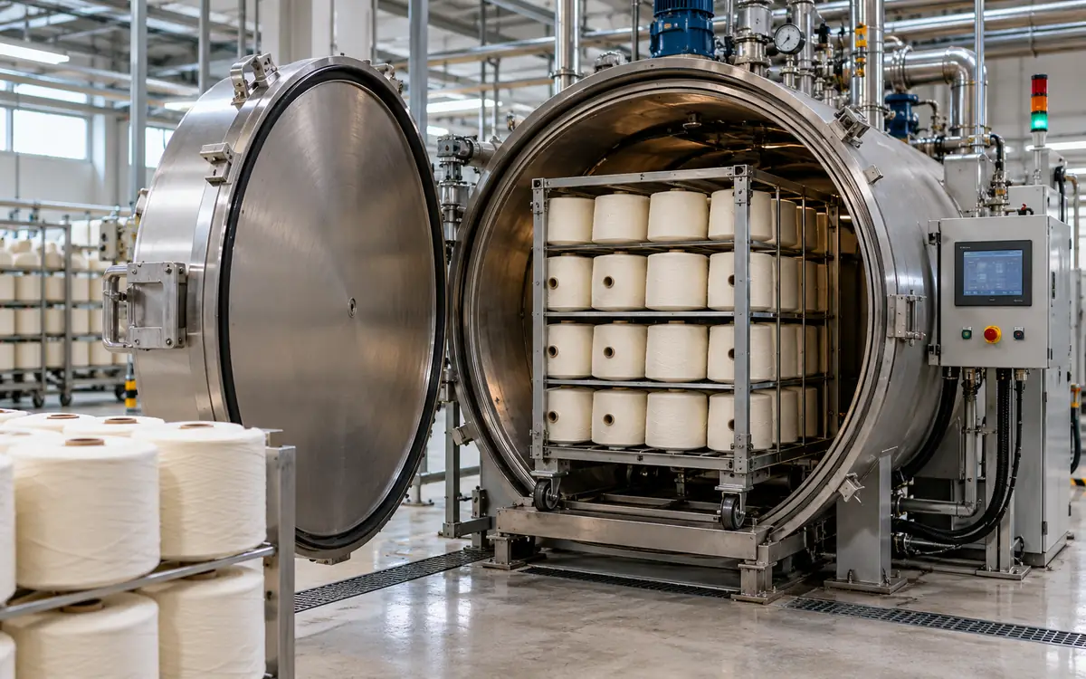
A typical system has a treatment vessel with a door and lock. It also needs a vacuum system, heat supply, and loading method. Instruments and controls manage the cycle. Its exact design determines the approved cycle.
The Jogson yarn-conditioning brochure describes the process in stages. After loading and door locking, a pump removes air. Steam treatment follows, with a further vacuum stage. It also shows heating coils, optional cooling, and several carrier arrangements. These details describe that manufacturer's system. Other designs may generate or distribute steam differently.
The initial vacuum reduces the amount of air in the vessel and load. Steam can then enter under the conditions set by the approved programme. Some cycles repeat vacuum and steam stages. The final stages bring the load to its required state. They also prepare it for safe release.
Do not reduce that sequence to “more vacuum gives better yarn.” The process includes vacuum level, heating rate, temperature, and time. Load and material matter too. Changing one can alter how the others work.
A useful cycle record includes actual measured values over time. A recipe name cannot show if the machine reached its targets. It cannot show the time taken or an alarm that stopped treatment.
The parts to identify on the installed machine
System | Why it matters | Information to retain |
Vessel and door | Contain the treatment environment and permit loading | Rated limits and approved access sequence |
Vacuum system | Remove gas from vessel and load | Pump type, measured pressure, evacuation time |
Heating system | Supply heat under controlled conditions | Steam or electrical supply and temperature record |
Drainage and condensate handling | Remove water where the design requires it | Approved checks and any abnormal discharge |
Load carrier | Hold packages in the validated arrangement | Carrier drawing, package count, total mass |
Instruments and controller | Measure and control the cycle | Calibration status, programme version, alarms |
Use the manufacturer's manual to trace the real arrangement. A generic diagram cannot establish where a valve, sensor, or safety device belongs.
Understand why low-temperature steam is possible
Water's saturation temperature depends on pressure. Below normal atmospheric pressure, saturated steam can exist below 100°C. That is the physical basis for low-temperature vacuum steaming.
The NIST saturation table gives water's saturation pressure as 0.019946 MPa at 60°C and 0.047414 MPa at 80°C. Converting MPa to kPa gives 19.946 kPa and 47.414 kPa. These are absolute pressures for the stated equilibrium condition.
Temperature | Saturation pressure | Pressure basis |
60°C | 19.946 kPa | Absolute |
80°C | 47.414 kPa | Absolute |
These values explain the relationship; they are not recommended yarn-treatment settings. A mill still needs a validated recipe for its fibre, finish, twist, package, and equipment.
Also distinguish vessel conditions from yarn conditions. A sensor may measure the chamber well before the centre of a load reaches the intended state. A temperature trace from one point cannot prove uniform treatment everywhere.
The presence of air adds another complication. Spirax Sarco's steam-quality guidance explains that total pressure in an air-and-steam mixture includes both gases. The steam temperature may then be lower than a pure-steam table suggests for that total pressure. Air removal and valid temperature measurements both matter.
Absolute pressure and gauge pressure are not the same
An absolute-pressure scale starts at perfect vacuum. A gauge-pressure scale uses the local atmosphere as its reference. Spirax Sarco's engineering-units guide explains the relationship.
Gauge pressure = absolute pressure − local atmospheric pressure
For this example, use 19.946 kPa absolute. Assume atmospheric pressure is 101.325 kPa:
Gauge pressure = 19.946 − 101.325 = −81.379 kPa
Now keep the same absolute pressure but assume the local atmosphere is 90.000 kPa:
Gauge pressure = 19.946 − 90.000 = −70.054 kPa
The physical absolute-pressure target is unchanged. The gauge reading is different because its reference changed.
An instruction such as “use 80% vacuum” needs more detail. Define the percentage and its pressure reference. Record the unit and pressure basis beside every setpoint and measured value. Ask the supplier to explain unclear labels. Resolve them before comparing machines or transferring a programme.
Do not change a setpoint to hide a suspected instrument error. Use the approved checks. Confirm the instrument type and calibration. Check its connection and displayed units too. Otherwise, the apparent correction can hide the actual fault.
Select the machine around the required duty
Different models offer different treatment ranges and load arrangements. FONG'S describes XORELLA Smart as a standard low-temperature range with applications up to 95°C. Its XORELLA Select page describes custom vessels with applications up to 140°C. Different doors and loading systems are offered for these vessels.
These are manufacturer-stated application limits for named ranges. They do not mean that every yarn should be treated at those temperatures. Nor do they establish the safe operating limits of a particular installed vessel.
Begin a purchase brief with the yarn and logistics. State the fibre blend, yarn count, twist range, and finish or wax. Give the package size and density. Describe the carrier and expected batch mass. Include the largest and smallest routine loads.
Then state the required output and shift pattern. A vessel may be large enough for the load. It can still lose time while waiting for a trolley. Another may suit the treatment but not fit the mill's doorway. Check the handling equipment too.
Ask for utility requirements at the agreed duty. Distinguish connected electrical load from measured consumption per cycle. Record whether vacuum-system cooling water is needed and how it will be supplied. Include start-up and part-load operation in the discussion.
Put the planned yarn range in the purchase trial plan. List which blends, finishes, and packages the supplier will demonstrate. Mark the untested cases as open items. A successful cotton load supports that load's result. A different blend remains an open question. Agree how to close each gap. The trial can then show whether the machine meets the agreed duty.
Loading is a controlled variable
A batch is more than its total kilograms. The package arrangement affects what the treatment system must reach. Record the package count, size, and winding form. Mark the carrier positions. Include any approved packaging used in the vessel.
Keep a loading drawing with the recipe. Mark spaces that must remain clear under the supplier's instructions. Record how packages are supported and which direction they face. Make the drawing specific enough that another shift can reproduce it.
Do not assume that two loads of equal mass are equivalent. A load of many small packages may differ from one containing fewer large packages. A tightly wound package may need a separate assessment from a softer one.
For development trials, choose positions that challenge the process. Include the centre and outer parts of the carrier. Sample different heights. Check packages near and far from relevant flow paths. The exact sampling plan should follow the machine design and the risk being tested.
Keep yarn identity visible. Mixed loads are only useful when the approved programme suits every included product. Two yarns may need different limits. Combining them just to fill the vessel may cause rework. That cost can exceed the cycle-time saving.
A load trial that can reveal uneven treatment
Start with a matched lot. Keep one group as a control and process another under the proposed programme. Record the starting condition of both. Use the same sampling and testing rules. This gives a firmer basis for linking a difference to treatment.
Make a sample map before unloading the treated batch. Choose several carrier points. Mark the packages to check in depth. Where the agreed method allows, retain outer, middle, and core yarn as separate samples. Keep both carrier position and package depth on every result. A poor result can then be traced back to its source.
Review the cycle trace and the product results in separate columns. Did the machine follow the programme? Did the yarn meet the agreed limits? The two columns need an answer before the process is approved.
The following results are hypothetical. They use moisture regain. This is water mass divided by dry textile mass, expressed as a percentage. Assume the team sets a trial target of 6.0%. Its internal development band is 5.5–6.5%. That band is invented for this example. It is not a standard commercial allowance.
Sample location | Trial A regain | Trial B regain |
Outer yarn | 8.0% | 6.2% |
Middle yarn | 6.0% | 6.0% |
Core yarn | 4.0% | 5.8% |
Simple mean of equal test portions | 6.0% | 6.0% |
Highest minus lowest | 4.0 percentage points | 0.4 percentage points |
Both trials have the same mean. Trial A has a large location difference and fails the assumed band. Trial B's three results fall within it. The mean alone would hide the first problem.
This table is not a statistical acceptance plan. It shows why location matters. Test enough samples to study the variation. Repeat the load trials before approving the process.
Choose the right moisture method
Moisture content and moisture regain use different denominators. Confusing them can make a correct measurement look like a failed treatment.
For a simple example, assume a textile sample contains 100 g of dry material and 6 g of water. Its total mass is 106 g.
Moisture regain = 6 g ÷ 100 g × 100 = 6.00%
Moisture content = 6 g ÷ 106 g × 100 = 5.66%
Both describe the same sample. Put the term and method on the report. ApparelDiary's article on moisture regain and receiving-weight checks explains the wider weighing distinction.
ASTM D2654-22 covers several moisture procedures with different uses. Its public scope distinguishes routine process-control approaches from methods suited to other purposes. It also warns that oven mass loss can include volatile material other than water. That matters when a yarn carries a finish.
Select the procedure with the laboratory. An oven loss and a handheld meter
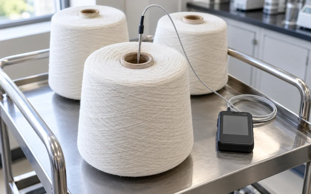
reading may answer different questions. Do not treat them as the same result. Preserve sample mass, timing, location, handling, and test conditions.
A moisture gain is not the same as a gain in dry fibre. Keep product-performance validation separate from commercial mass rules. Use the contract and relevant rules to establish the sales-mass basis.
Test the behaviour that justified the machine
If the project aims to improve knitting performance, run a controlled knitting comparison. If the problem is snarling, use a defined assessment that can be repeated. A moisture result is useful, but it is only one part of the evidence.
For tensile testing, ISO 2062:2009 covers single-end breaking force and elongation. It uses a constant-rate-of-extension tester. Its scope has exclusions, so the laboratory must confirm that the method fits the yarn. The published standard remains listed while a revision is under development.
Use the same relevant test atmosphere and method for the comparison. Record when samples were taken and how they were held before testing. A newly treated sample may still be warm. The control may have equilibrated in the laboratory. Such a comparison can confuse the treatment effect with the test condition.
Report both the raw measurement and any derived result. If tenacity is used, keep the linear-density basis clear. Do not infer a durable improvement from one higher breaking-force value.
A downstream trial also needs a fair denominator. Suppose control yarn gives 40 breaks over 2,000 position-hours. Treated yarn gives 30 breaks over the same exposure.
Control break rate = 40 ÷ 2,000 × 1,000 = 20 breaks per 1,000 position-hours
Treated break rate = 30 ÷ 2,000 × 1,000 = 15 breaks per 1,000 position-hours
Observed rate reduction = (20 − 15) ÷ 20 × 100 = 25%
This is a hypothetical observed difference. It does not prove statistical significance or a guaranteed saving. Repeat the comparison. Examine machine settings, shifts, and yarn lots. Check other possible causes too.
Calculate output from the complete batch cycle
A treatment hold time is only part of the batch duration. Include loading, door operation, evacuation, heating, holds, final stages, and unloading. Use the actual sequence so that overlapping tasks are not counted twice.
Consider a hypothetical 600 kg batch. Loading and unloading together take 15 minutes. The recorded machine cycle takes 55 minutes. Assume those periods do not overlap.
Total batch time = 15 + 55 = 70 min
Nominal throughput = 600 kg × 60 min/h ÷ 70 min = 514.29 kg/h
If the available production time is 420 minutes, six complete batches fit:
Complete batches = 420 min ÷ 70 min = 6
Shift output = 6 × 600 kg = 3,600 kg
This result assumes each load is ready and every batch is accepted. Now suppose the shift loses 20 minutes. That leaves 400 minutes, enough for five complete 70-minute batches. The remaining 50 minutes may support preparation. They do not complete another batch under these assumptions.
Use that distinction when comparing quotes. A machine with a short hold time can still have a long total cycle. A larger vessel needs suitable loads. Filling it may require mixed products. If they need different treatment, the larger size may offer little benefit.
Measure energy and utilities at a clear boundary
Choose the study boundary. Will it cover only the conditioner? Will it include the plant supplying steam and cooling water too? Keep that boundary the same in every comparison.
Take an accepted 600 kg batch. Within the chosen boundary, it uses 180 kg of measured steam. Electricity use is 24 kWh.
Specific steam use = 180 kg ÷ 600 kg = 0.30 kg steam/kg yarn
Specific electricity use = 24 kWh ÷ 600 kg = 0.040 kWh/kg yarn
These are example measurements, not supplier guarantees. Keep the yarn mass basis the same. Treatment can change moisture and total mass.
Record utility use during idle and warm-up periods too. Allocate those periods clearly when reporting a shift result. Comparing a full-load steady run with a small first batch can create a misleading saving.
Measure water separately if the installed vacuum system uses it. Do not convert a connection size into a consumption figure. Ask for an appropriate meter or a verified measurement method.
Troubleshoot the pattern before changing the recipe
Symptom | First distinction to make | Evidence to review |
Long evacuation | Machine condition or changed load? | Empty and loaded approved checks, pressure trace |
Wet outer yarn and dry core | Uneven treatment or sampling error? | Location map, load pattern, test handling |
Repeated low-temperature alarm | Supply issue or measurement issue? | Utility record and calibrated sensor checks |
Normal trace but poor running | Wrong treatment objective or material change? | Matched control trial and yarn identity |
Higher batch mass only | Water uptake or real process benefit? | Moisture basis and downstream results |
Cycle time drift | Longer machine stage or handling delay? | Stage timestamps and trolley records |
Use supplier-approved diagnostic procedures. A pressure-hold or leak test has defined conditions and limits. Do not improvise one from a general article.
Use the sample map to choose the next check. Results that follow one carrier position point toward that location and loading arrangement. Results may follow a yarn type across several positions. In that case, review its material and recipe. If all points change, check the shared test method and utility supply too.
Retain the original trace before changing the programme. Check the actual vessel conditions and load against the approved record. When the evidence supports a cause, record the fix and repeat the needed trial. A longer hold may make the symptom disappear. It can also hide the fault and consume capacity. The record still needs to explain what changed.
Keep safe limits and maintenance separate from recipes
A production recipe is not the vessel's design rating. Keep within the approved pressure and temperature limits. Maintain the door controls and protective devices. Follow the access rules for the installed system.
In Great Britain, HSE's PSSR guidance identifies steam at any pressure as a relevant fluid. It also explains the need for examination arrangements for qualifying systems. Do not assume the word vacuum removes the need to assess the connected steam system. Determine the applicable duties for the actual installation.
Plan maintenance for the complete machine. Include the door seal, vacuum system, heating and drainage equipment, instruments, and controls. Use the supplier's intervals and approved procedures. Record findings that may explain changes in cycle time or product results.
A safe door-release indication is part of a validated system. Do not bypass an interlock because a display appears to show a harmless value. Trained, authorized staff must handle servicing and fault recovery. They need to follow the correct isolation and verification process.
Questions to settle before production approval
Can one programme cover all cotton yarns?
Only if trials support the defined product range. Yarn count, twist, finish, package size, and winding condition can differ. State the boundaries of the approved family.
Does reaching the chamber temperature prove treatment is complete?
No. The chamber trace and product evidence answer different questions. Validate the load, including demanding package positions, against the intended result.
Should treated yarn be tested immediately?
Use the agreed test method and sample-handling plan. Record timing. Laboratory conditioning may be required for the property comparison, even after industrial conditioning.
Is more added water always better?
No. The goal is the agreed product condition and useful performance. A higher mass alone does not show even treatment or better running.
Make the approval usable on the next shift
The approval record names the yarn range and shows how to load it. It states the programme and yarn limits. It shows what the machine did and how the yarn behaved after the cycle. Clear pressure units and sample points help the team read both records.
The next shift also needs the allowed boundaries. A change in package density, load mix, or treatment objective may need review. Calculate capacity from the full batch sequence. Use the stated measurement boundary for utility figures. The mill can then judge a change against a process it knows.
Conditioning affects yarn handling, so see yarn package winding, yarn twist and yarn clearing.

Discussion0
Loading the discussion…