
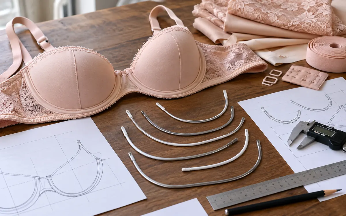
An underwire that looks right on a drawing can still fail in a finished bra. The wire may sit at the wrong angle, open too far under band tension or press against an end closure. Changing the cup label alone will not explain those problems.
Start by checking how the wire, its fabric channel and the rest of the bra work together. Shape, stiffness, orientation and clearance all need a defined meaning. Record these features with each sample. Then the next change has a clear purpose.
This guide focuses on wired bra frames and their fit. It does not provide a universal drafting block or a set of mandatory dimensions. The numerical examples are hypothetical engineering exercises, with assumptions shown.
Treat the wire as part of the assembly
The wire follows the lower edge of the cup. The channel holds it within the bra. The cradle or frame surrounds the cup base in a full-band bra. The bridge joins the cups at the centre front, and the wings extend towards the back fastening.
These parts interact under tension. A flat wire trace therefore describes only one state of the component. Its shape in a worn bra also depends on the parts around it.
Madalynne's drafting guide explains how tension in the band opens a flexible wire. It also explains full-band and partial-band bras. A partial-band bra lacks a frame that runs all the way beneath the cups. The two designs place the channel in different ways. Their cup patterns need changes before they can be exchanged. Source: Madalynne.
Name the type of bra before discussing the wire. “Standard underwire bra” is too vague when the team is comparing a low plunge, a full-cup bra and a strapless style.
A useful question is, “What must this assembly do during the intended activity?” That question links the choice of parts to the wearer and the product brief.
Give every wire a complete identity
A wire number is an order code within a supplier's range. It is not a measurement. The same number from another supplier does not prove that its wire will fit.
AFI Atelier explains that patterns are designed around particular wire shapes and lengths. Its guidance recommends checking both rather than relying only on the stated bra size. The wrong shape can matter more than a small change in length. Source: AFI Atelier.
Build a component record with the supplier, style name, size code, drawing revision and approved sample. Include the material and coating description supplied for that product. If the tip colour marks the centre front, record that rule as well.
Emerald Erin, for example, identifies the coloured tip as the centre-front end of its listed fitting-pack wires. Its page also states the material and coating for those products. Those details belong to that range; another supplier may use a different marking system. Source: Emerald Erin fitting pack.
Keep a physical sample when approving a new source. A purchasing note that says “same size, different vendor” leaves the sample room to discover any hidden differences.
Read wire geometry in several dimensions
One length cannot describe a curved part. Two wires may have similar arc lengths while differing in width, depth and the height of their ends.
Place each wire the same way. Record the sizes that answer the design question.
Feature | What to record | Why it helps |
Arc length | Path and measuring convention | Checks the length inside the channel |
Opening width | Distance between defined end points | Compares the relaxed spread |
Depth | Lowest point to a stated reference line | Distinguishes deep from shallow shapes |
Centre-front height | Defined lower reference to front tip | Connects the wire to the neckline and bridge |
Underarm height | Same lower reference to outer tip | Helps assess side coverage |
Cross-section | Supplier dimensions and orientation | Identifies the component beyond its outline |
Tip finish | Cap or coating condition | Checks the part that meets the channel ends |
Keep the reference lines on the drawing. Without them, two correct readings can still describe different things.
For instance, a straight distance between tips is not the wire's arc length. Measuring around its outer edge also follows a different path from its centre line. Choose one method, label it and use it consistently.
Compare shape families without turning names into standards
Suppliers use names such as plunge, round, vertical or balconette to describe their ranges. These names help a buyer search the range. The drawing gives more precise details.
Emerald Erin's range illustrates the difference. Its Plunge wire has a low centre front, while Bliss is described as deeper and narrower than its classic day-bra wires. France has a shallower, more splayed form. These comparisons apply to that supplier's range. Other ranges may use the same names in other ways. Source: Emerald Erin.
Compare the outlines at the same scale. Ask which differences matter to the proposed bra. A lower front tip may suit a lower neckline. It also changes the frame area that needs to be checked.
Avoid selecting a wire by appearance alone. A photo can hide scale, angles and spring behaviour. An outline, wire sample and sewing trial each provide useful evidence.
If the design changes from a full-cup style to a plunge, return to the wire choice and frame relationship. Do not assume that trimming the visible neckline completes the conversion.
Check drawing scale before assessing fit
Printable charts are useful only when their size is preserved. Emerald Erin explicitly instructs readers to print its wire charts at actual size and check the printed ruler. Source: Emerald Erin wire charts.
A printout at 95% can create a false mismatch. Consider a hypothetical reference line specified as 100 millimetres. If the printed line measures 95 millimetres, the scale factor is:
Scale factor = printed reference / stated reference = 95 mm / 100 mm = 0.95
A 140-millimetre opening shown at that scale becomes 133 millimetres. The apparent seven-millimetre gap comes from the print setting.
Printed opening = 140 mm × 0.95 = 133 mm
Reprint at the correct scale before comparing a wire. Do not resize the pattern to make it match a printout whose scale is wrong.
This check is quick enough to include in sample-room intake. Mark the verified reference on the sheet and keep its revision date with the component record.
Separate wire spring from wire play
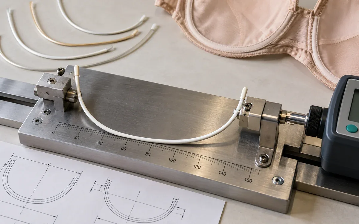
Wire spring describes how the wire opens or changes shape. The wire's flexibility and the frame shape both matter. Wire play is the spare space near the wire ends inside the finished channel.
These solve different problems. Spring concerns shape under load. Play concerns free space along the channel.
Van Jonsson makes this distinction in a guide to drafting the cradle. The author gives starting values from her own work. The article also states that those starting points should be adjusted after fittings. Treat them as a method example, not a requirement for every bra. Source: Van Jonsson Design.
A note reading “add eight millimetres for the wire” is therefore incomplete. Is that an end extension, a closing allowance, an offset for spring or a total across both ends?
Write the purpose beside the dimension. Keep seam allowance separate from the free space inside the finished channel. Fabric folded or cut away during sewing cannot be counted as space for the wire.
Define spring with a reference condition
Suppose a hypothetical wire has a relaxed opening width of 124 millimetres between two marked points. In a development fixture, the target opening is 136 millimetres.
Opening change = 136 mm - 124 mm = 12 mm
That sum records a change in shape. It does not state the force needed to reach the target. It also cannot tell us the pressure on the body or how the bra feels.
The fixture also matters. Holding one end while moving the other is different from moving both ends. Rotating the wire while measuring can change the reported width without producing the intended shape.
State which point stays fixed, which point moves and along which line. Then photograph or sketch the setup in the internal development record so another technician can repeat it.
If a supplier describes a wire as firm or flexible, ask for the comparison basis. A useful answer names the tested component and method. An adjective alone cannot support a numerical substitution.
Use a force-displacement comparison carefully
A bench test can compare two wires when the setup is kept the same. A trained technician should plan and run the test with a suitable fixture and force gauge.
For illustration, assume the same fixture is used for both wires. Record the increase in opening from the relaxed state at two force levels.
Candidate | Opening increase at 6 N | Opening increase at 10 N |
A | 8 mm | 14 mm |
B | 6 mm | 10 mm |
To find stiffness over this interval, divide the change in force by the change in opening.
k = (F2 - F1) / (x2 - x1)
For candidate A:
kA = (10 N - 6 N) / (14 mm - 8 mm) = 0.667 N/mm
For candidate B:
kB = (10 N - 6 N) / (10 mm - 6 mm) = 1.00 N/mm
In this example, B needs more added force for each added millimetre of opening. That applies only to the measured interval. That is the limit of the conclusion.
This is not the material's Young's modulus, and the result should not be extrapolated across all displacements. It includes the effects of the wire shape and the test setup. It also does not prove which wire gives better support or comfort in a bra.
Align the wire and cradle at the correct line
A cutting edge includes allowances. These do not mark the final wire position. Compare the wire with the intended wire line, following the pattern's construction method.
AFI's method joins cradle pieces at their sewing lines and aligns the lower bowl of the wire with the lower curve. It warns against beginning the comparison by matching whichever tip seems convenient. Source: AFI Atelier.
For a sample-room review, mark the lower reference point, front tip and underarm tip. Also identify the wire's intended rotation and the channel position relative to the seam.
Then inspect the entire curve. Matching the lower reference and both ends does not guarantee that the middle sections agree. A local flat spot or tight curve may still need attention.
The same rule applies to other garment pattern marks. Check what each line means before using it to make a sewing decision.
Calculate clearance from the finished channel
Channeling encloses the wire and helps keep the cup-to-frame area stable. Orange Lingerie's explanation of bra notions discusses both functions. Its sewing advice also allows space for wire movement and closing the channel. Source: Orange Lingerie.
Use the finished usable path for a clearance calculation. The raw cut length may include folds, joining allowances or end closures.
Consider a hypothetical channel with a finished overall path of 280 millimetres. Each end closure occupies three millimetres along that path. The usable space between the closures is therefore 274 millimetres.
Usable channel = 280 mm - 3 mm - 3 mm = 274 mm
If the coated wire measures 260 millimetres along the agreed path:
Total nominal play = 274 mm - 260 mm = 14 mm
If the wire is centred, that corresponds to seven millimetres at each end. In use, the wire may move, so equal clearance at every moment should not be assumed.
These values illustrate the accounting of space. They are not recommended minimums or an approved construction specification.
Add tolerance and wash change to the example
Nominal sizes are the stated target values. They do not show the least free space the sewn bra could have. Suppose the hypothetical usable channel is specified as 274 ± 2 millimetres and the wire as 260 ± 1 millimetre.
The shortest allowed channel and longest allowed wire give:
Minimum initial play = (274 - 2) mm - (260 + 1) mm = 11 mm
Now assume a development test measures a 2% reduction in the usable channel path after the chosen care cycle. This is an invented scenario, not a typical shrinkage value.
Using the shortest initial channel:
Post-care channel = 272 mm × (1 - 0.02) = 266.56 mm
Remaining play = 266.56 mm - 261 mm = 5.56 mm
The original nominal play was 14 millimetres, but this combined case leaves 5.56 millimetres. To decide if that is suitable, set a product requirement and check the sewn sample.
The model assumes the path shrinks evenly and the wire length stays the same. Real seams and closures may behave differently. Measure the finished sample after care instead of treating the arithmetic as a substitute for testing.
Evaluate the bridge as a shape
The bridge has a height, widths at different levels and an angle relative to the frame. One top-width measurement does not describe the whole piece.
LilypaDesigns shows two bridge options with the same width at the top but different geometry. Its discussion also explains that adding or removing a wedge can alter the angle of the surrounding band. Source: LilypaDesigns.
For an original development record, measure top width, lower width and height at defined lines. Record the front wire angle beside these measurements. This makes it possible to distinguish a width change from a rotation change.
If the bridge does not sit as intended, do not assume it is the only cause. Check the cup, wire and band together before cutting a wedge.
A narrowed bridge may change how the wires sit without solving a cup-depth problem. Conversely, changing the cup while ignoring the bridge can leave the same central pressure point. The next trial should test a stated explanation.
Build a controlled fitting sample
A fitting sample must use materials and sewing methods close enough to the planned bra. Otherwise, it may not answer the current question. Mark any changed parts, especially those that affect stretch, channel size or seam bulk.
For an initial wire comparison, keep the cup, frame, band materials and fastening position consistent. Change the wire only if both candidates can be assembled with the required clearance.
If one wire requires a new cradle, record that as a combined change. It may be the right choice, but it changes more than just the wire.
Use a brief fitting sequence with standing, sitting and ordinary arm movements. Ask the wearer to describe location and sensation, then note whether the garment shifts. Stop a trial that causes pain or exposes a damaged wire.
A flat reference photograph cannot capture all these observations. Record the state of the bra and the wearer's comments together. A single approval tick loses those details.
Diagnose symptoms through competing explanations
The following table is an editorial investigation aid. It proposes questions to test rather than assigning a guaranteed cause.
Observation | Plausible area to inspect | Evidence for the next decision |
Front tip presses | Tip height, rotation, bridge or cup relationship | Location during the same movement |
Underarm tip rubs | Outer height, opening or frame position | Comparison with one controlled change |
Wire moves inside the channel | Available play and end closures | Finished path and closure locations |
Wire breaks through casing | Tip condition, clearance, stitching and wear | Failed sample examined before repair |
Lower frame wrinkles | Wire-to-curve match and assembly tension | Pattern overlay and sewn sample |
Bra shifts downward | Combined cup, wire and band fit | Before-and-after movement observations |
One side differs | Component pairing, sewing variation or wearer fit | Left/right records without assumptions |
Do not repair away the evidence before recording a failure. Keep the original wire, casing and stitching where possible, then note the point of damage.
If several changes are needed, identify which are confirmed corrections and which are still trials. That distinction helps the next technician understand why the new sample exists.
Investigate wire breakthrough at assembly level
A wire emerging from its channel should trigger a review of the complete failure path. Replacing it with a shorter wire may restore space, but it does not establish why the original sample failed.
First inspect the tip coating and any sharp damage. Then locate the channel end, the closing stitches and the available path. Check whether the wire was the approved component and inserted in the intended direction.
Compare the failed sample with an unused reference and, where available, a sample after the same care history. Record any path change or local wear before deciding what to alter.
The review may find a wrong part, too little space, damaged coating or poor sewing. More than one cause may still be possible. Rebuild a sample to test each likely cause.
Avoid describing a repaired sample as validated merely because the wire can be inserted again. The revised assembly needs the relevant fit, movement and care checks.
A sample-room case: the right number on the wrong wire
Consider a hypothetical factory making a second sample of a full-cup bra. The first sample fitted well. On the second, the wearer reports pressure near the outer tip, although the fabric pattern has not changed.
The technician first checks the sewing and finds that the channel follows the approved line. The two wire packets both show size 42, so the team initially rules out the wire.
An overlay tells a different story. The second packet came from another supplier. Its outer tip sits higher when the lower bowl and front reference are aligned. The number 42 identified a place in each supplier's range; it never promised the same outline.
The team keeps the failed sample intact and makes a controlled comparison with the approved wire. If that trial resolves the pressure point, it supports the component-mismatch explanation. It does not prove that the replacement supplier's wire is defective. That wire may suit another frame.
The corrective action is specific: restore the approved supplier code in the sample-room kit, then assess the alternative wire as a separate development option. Merely writing “use a softer wire” would miss the confirmed difference in geometry.
This case also shows why a purchase substitution should reach the pattern and fitting teams. A price or stock decision can change the part that a previously approved frame was built around.
Read research without turning a result into a rule
Research supports the value of studying individual geometry, but it does not supply one wire for every wearer.
Wang and Suh tested custom 3D-printed wires against standard wires in wear trials. They published their paper in 2019. The public abstract reports gains in pressure and in how support or comfort felt. These results apply to the study conditions. It also compares wire lengths. Pressure and the wearers' reported sensations did not change in the same way. Source: Wang and Suh.
The useful design lesson is to measure several outcomes. Lower pressure at one location, perceived comfort and garment stability are different results.
Sun and colleagues used a finite-element model to study the contact between the body and bra. They examined shape and pressure. Its model uses defined body geometry and material assumptions. The results apply to that model and the trial used to check it. They do not give a performance ratio for all wired and wireless bras. Source: PolyU research record.
A digital model can help screen design questions. Physical samples and wearer trials still need a clear role in the development plan.
Release a component specification that can be followed
Keep the approved wire drawing and sample with the frame revision and sewing instructions. Include the usable channel measurement method and the acceptance criteria chosen for the product.
List the approved alternative components explicitly. If substitution requires a new cradle or changed closure position, that requirement belongs in the release notes.
Record what was tested, on which samples and under which conditions. Approval of one sample does not prove that every size or future batch of wires will behave the same way.
Use garment specification control to keep measurements, revisions and sewing notes linked.
Check the wire instructions through a readback. Which part is used? Which way does it face? What path and final free space must be checked? If the operator cannot answer those questions from the file, the specification is still incomplete.
Frequently asked questions
Is a larger wire number always wider?
Not across suppliers and styles. Consult the relevant drawing and compare the dimensions that matter to the product.
Can I add the same spring to every wire?
A fixed allowance may suit one drafting method. Check the wire and bra before using that value elsewhere. Define how the opening is measured and confirm the finished sample.
Is wire play another name for seam allowance?
No. Wire play is available space in the finished channel. A seam allowance may be folded, stitched or trimmed, so it cannot be counted as free space without checking the construction.
Does a firmer wire give better support?
The bench comparison describes component behaviour under a defined load. Support and comfort belong to the complete bra on the wearer. A firmer component is not automatically the better choice.
Can a digital wire trace replace a fitting trial?
It can verify geometry and support a comparison. It cannot establish how the whole bra feels or behaves during movement.
Make each adjustment explainable
Choose the wire with the frame and intended use in view. Keep its identity, check the drawing scale and record how it opens. Measure the free space at the ends as a separate check.
Then compare the actual assembly under controlled conditions. A good development record explains what changed, why it changed and what the next sample showed. That is how wire selection becomes a repeatable engineering decision.
Fit engineering relies on components and measurement, so see narrow elastic testing, choosing garment linings and how to measure garments.
References
Wang and Suh, 2019: Bra Underwire Customization with 3D Printing. Public abstract.
Sun and colleagues, 2019: 3D Bra and Human Interactive Modeling Using Finite Element Method. Institutional abstract and publication record.

Discussion0
Loading the discussion…