
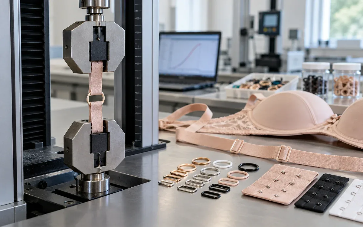
A bra slider can remain in one piece and still fail its job. It may let the strap move during wear. A hook can resist a high pull yet feel hard to close. A ring can look sound while its rough edge damages the strap.
Bra hardware testing therefore needs several clear questions. Strength, adjustment, repeated use, finish and the sewn attachment are related, but they are different properties. One peak-force result cannot describe them all.
This guide explains how to build a component test plan for rings, sliders and hook-and-eye closures. It combines verified source scopes with original development methods and worked examples. The example forces, cycle counts and limits are hypothetical. They are not universal bra specifications or a substitute for the buyer's approved method.
Define the component and its job
Start with the full assembly. Identify the component, the material it touches and the direction in which it carries load.
For a ring, the useful question may be whether it bends, cracks or damages the folded strap. For a slider, it may be whether the strap holds its set length. For a closure, it may be whether the hooks stay engaged and the backing remains intact.
Prym Intimates' rings and slides range illustrates the material choices. It includes plastic, nylon-coated metal and electroplated parts in varied forms and sizes. These are product categories, not proof that each version suits every bra.
Record the supplier's exact part code. Add the inner opening, bar shape, material, finish and approved drawing. A colour name or an outer width is not enough to define a slider.
For hook-and-eye tape, record the number of hooks, eye rows, spacing, tape width and backing. Prym's hook-and-eye range includes both basic designs and a hidden-stitch construction, with a padded option. That illustrates why the textile backing belongs in the review. A description of comfort is still a manufacturer's claim.
Photograph both sides of the assembled part. Show the strap path through the slider and the fold around the ring. A reversed path can change the test even when the parts have the same code.
Separate failure modes before choosing equipment
Write the failure you want the test to reveal. Then choose a method that can observe it.
Failure mode | Useful observation | Important distinction |
Ring opens or cracks | Force and location at the first defined failure | Metal or plastic failure differs from strap rupture |
Slider bar bends | Shape change under and after load | Peak force alone may conceal early distortion |
Strap moves through slider | Mark movement during a set load sequence | Movement differs from elastic stretch |
Hook opens or disengages | Load, direction and eye row used | Opening is different from pulling the tape apart |
Eye pulls out of backing | First pull-out event and backing damage | Component attachment differs from the outer sewing seam |
Closure seam breaks | Seam location, stitches and force | The assembled bra has failed even if the hardware survives |
Finish flakes or stains | Surface and adjacent fabric after exposure | Appearance does not establish nickel release |
This table is an original planning aid. Select the relevant rows for the actual product. It does not assign pass limits.
A test intended to isolate a ring may use a controlled support tape. A test intended to validate the bra should use the approved strap and sewing route. Those tests answer different questions. Keep their reports separate.
A seam failure may stop an isolated hardware test before the component breaks. Record that limit. Do not label the unseen component breaking force as if it had been measured.
In the assembled-use test, the same seam failure is part of the product result. Discarding it would hide the weakest part of the system. ApparelDiary's seam failure guide provides a companion approach to locating the cause.
Make the test brief specific enough to repeat
Before testing, agree the sample identity, method and decision rule. Record who approved the plan and which product it covers.
The method should state the fixture, load direction, gauge length and speed. It should also define any starting load, hold time, cycle profile and recovery period. Add the care state and the event that ends the test.
The acceptance rule needs the same precision. A minimum breaking force differs from a maximum slip value. A rule for no sharp fracture differs from a rule for no permanent bending.
Use the buyer's current specification where one applies. Check its revision and scope. An online method's machine speed or sample count does not become a universal industry requirement.
Set aside specimens for each planned route. A destructive pull changes the part. It should not then be used as an untouched sample in a wash or comfort comparison.
Keep a simple sample map. Each row should identify the part lot, strap lot, assembly revision and planned test. Mark whether the sample is new, washed or already cycled. This prevents an attractive average built from unlike conditions.
Check the force system and the textile conditions
A tensile machine is useful only when its readings and setup suit the task.
ISO 7500-1:2018 covers calibration and verification of static tension and compression force systems. Its public scope notes that static calibration values are not necessarily valid for high-speed or dynamic work. The standard is an equipment reference, not a bra hardware pass limit.
Check the calibrated force range used for the test. Confirm that the load cell, fixtures and software settings match the agreed method. A large machine capacity does not by itself show that the small forces of interest are measured well.
Inspect grips before mounting. Prevent slipping without crushing the part or cutting the support tape. Keep the intended load path centred. Record a fixture change because it can alter the failure location.
Condition the textile parts as the method requires. ISO 139:2005, with its listed amendment, addresses atmospheres for textile conditioning and testing. It also allows agreed alternative atmospheres within its scope. Record the actual conditions and the method followed.
Do not copy a fixed conditioning time from an unrelated procedure and assume it proves equilibrium. Ask the lab to apply the appropriate requirement to the assembly.
Use the machine's guards and the lab's trained operating procedure. Small broken parts can leave a fixture suddenly. Stop and investigate a shifting grip rather than reaching into a loaded test.
Check that the mounting method can be repeated
Before a large supplier comparison, run a small setup trial. Ask two trained operators to mount matched samples independently. Give both the same written method. Keep the part lot, strap and care state alike.
For a destructive test, each mounting needs a fresh specimen. Reusing a part that has already bent would confuse operator effects with earlier damage.
Compare the mounting photographs, force traces and failure locations. Suppose one operator sees tape rupture at the grip while the other sees ring deformation. Check jaw pressure, alignment and support length before treating the results as a supplier difference.
Revise the method where it leaves room for conflicting setups. Then repeat the affected comparison with fresh samples. Preserve the first results and explain why the setup changed.
This is an original development check, not a prescribed sampling plan. Its purpose is to expose an unclear fixture or instruction before many specimens are used.
Check geometry before testing strength
Measure the opening that the strap actually uses. Check the internal width and the space around the centre bar. Inspect the edge shape where the folded material bends.
A nominally matching strap and slider may still form a poor pair. The strap can bunch, twist or fold at the slot. The centre bar can press into a bulky seam or catch a surface yarn.
Make a small fit card for each proposed pair. Record strap width and thickness under the stated measuring conditions. Note the number of layers at the attachment. Show the thread path and the position of the sewn fold.
Thread the sample as it will be worn. Move the slider through its intended range. Check whether the strap can be adjusted without turning the component or forcing a fold through it.
Inspect the least and most adjusted positions. One end may place a thick join near the slider. Another may leave too little free tail for the intended use. Define those limits in the pattern and assembly instructions.
If the strap changes, repeat the fit check. A wider strap is an obvious change. A new finish or thickness can also alter the pair. ApparelDiary's narrow elastic testing guide helps describe the strap's own force and recovery behaviour.
Run an isolated strength test and report its limit
Use the agreed fixture and support material to load the component. Record the mounting arrangement before the first pull.
Define the first reportable event. It may be opening, a crack, permanent deformation or a stated amount of displacement. Continue to a later break only when the method calls for it and the setup remains valid.
Retain both the force trace and the observed failure mode. A smooth rise followed by tape rupture is different from early component bending followed by a later peak.
Suppose the support tape breaks at 92 N while the ring remains intact. The test has shown that this mounted ring withstood 92 N up to that event. It has not measured a ring breaking force of 92 N.
The next step depends on the question. A controlled component comparison may need a suitable stronger support. A finished-assembly test should retain the tape failure as an assembly outcome. Do not silently switch between those interpretations.
Worked example: review a small force series
Assume a buyer has approved an illustrative minimum of 75 N for a particular assembly and care state. Five hypothetical valid failure readings are 84, 82, 89, 86 and 79 N.
Mean force = (84 + 82 + 89 + 86 + 79) N / 5 = 84 N
Observed range = 89 N - 79 N = 10 N
Lowest observed margin = 79 N - 75 N = 4 N
All five readings exceed the invented limit. The minimum result has only a 4 N observed margin. Apply the agreed decision rule, including any treatment of measurement uncertainty.
Five results are not a universal sampling plan. This calculation cannot establish a population failure rate or prove that every part in a shipment meets the rule.
Test slider holding as its own function
A slider test should show whether the set adjustment remains stable under the chosen use sequence.
Use the approved strap. Record its path, starting adjustment and free-tail length. Mark a point near a defined slider edge. Also mark a short reference length on the strap so that material extension can be observed.
Apply the agreed load pattern. This may involve repeated loading, a hold or both. State the load limits, rate and number of cycles. Do not describe a test merely as “pulled several times.”
Observe whether a mark actually feeds past the slider edge. Record rotation, bunching and surface damage. After the sequence, read the mark position under the same stated low preload and recovery conditions.
Worked example: position change is not automatically elastic growth
Suppose a mark is initially 18 mm from the selected edge. After the test, it is 23 mm away under the same reading conditions.
Mark position change = 23 mm - 18 mm = 5 mm
Report the signed 5 mm change and the chosen direction. Examine the strap's reference marks and the observed feed through the slot. The number alone does not establish how much came from feed, local stretch or component movement.
A useful comparison keeps the strap constant and changes one slider feature. A second comparison may keep the slider constant and change the strap. This
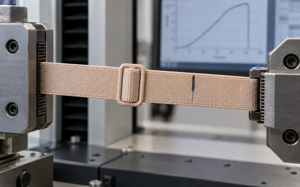
sequence helps locate a weak pairing.
Do not improve holding by making adjustment unreasonably hard. Include a separate use check for the intended adjustment task. A slider that stays fixed because it cannot be moved may fail the product brief.
Test the closure in the direction it is used
Hook-and-eye tape has several ways to fail. A hook can open, an eye can pull out, the tape can tear or the joining seam can break. The closure can also unhook during a change in load direction.
Engage the specified eye row. Record the number of hooks actually engaged. Mount the tape at the agreed width and direction. Avoid a fixture that supports the hooks more than the garment would.
A direct pull across the band does not answer every use question. A controlled angle change may reveal disengagement. Repeated opening and closing may reveal a different weakness. Define each route rather than combining them into one unclear test.
Do not assume equal force on every hook. If the machine reads 90 N across three hooks, dividing by three gives 30 N only under an equal-sharing assumption. It does not prove that each hook carried 30 N. Tape stiffness, alignment and engagement can alter the load distribution.
Inspect the backing after use. Look for exposed ends, local distortion and damage near the eye attachment. Check the seam that joins the tape to the bra as well as the tape itself.
Record opening and closing ease in a defined use task. A maximum-force test should not be used as a proxy for hand access or comfort.
Give cycle counts a clear meaning
A cycle must have a start and an end. For a closure, it could mean fully engaging and then opening the specified hooks. For a slider, it could mean one complete load-and-unload sequence.
State the count, rate, pauses and inspection intervals. Record an early stop and its cause. Do not reset the count after a jam and report only the successful part.
Consider a hypothetical closure trial of 2,000 cycles at 20 complete cycles per minute.
Nominal running time = 2,000 cycles / (20 cycles/min) = 100 min
This is machine running time. Setup, inspections and pauses add to elapsed time. It is not a claim that 2,000 cycles equal a certain number of months of wear.
Inspect the same features at planned intervals. Log hook shape, eye movement, tape wear and closing function. Preserve the sequence of observations so the final result has context.
If a fixture causes a failure that the use setup would not create, investigate it. Keep the original result and reason for any method change. Do not simply remove the inconvenient sample from the record.
Check care, finish and corrosion without confusing them
The whole assembly should face the care process chosen for the product. Include the hardware, strap, backing and attachment seams.
ISO 6330:2021 specifies domestic washing and drying procedures for textile testing. Its public scope includes machine, detergent and drying choices. Those choices can affect results. Identify the procedure and number of cycles rather than saying only that a sample was washed.
Keep new and cared-for results separate. Compare slider holding, closure function, surface condition and adjacent fabric. Record whether a closure was fastened and whether a wash bag was used, when these form part of the approved procedure.
A salt-spray result answers another question. ISO 9227:2022, with its listed 2024 amendment, covers defined salt-spray methods. Its scope leaves product exposure periods and result interpretation to the appropriate specification. It also warns against using the method to predict long-term corrosion resistance or rank different materials for that purpose.
Do not convert a number of salt-spray hours into years of bra wear. Do not treat an unchanged appearance as evidence of chemical compliance.
For a finish complaint, record where the change began. A damaged bend, exposed edge and broad surface stain suggest different follow-up questions. Compare the failed area with an untouched sample from the same lot.
Keep nickel release separate from metal content
A material declaration and a release test measure different things. A statement about alloy content does not by itself establish the release from a skin-contact surface.
The ECHA entry for nickel and its compounds identifies REACH Annex XVII Entry 27 and lists the relevant European standards. For the EU market, have the lab confirm the applicable skin-contact scope, restriction and current test route for the actual part.
The current BS EN 1811:2023 listing identifies the reference method for nickel release from the specified skin-contact articles. BS EN 12472:2020 addresses simulated accelerated wear and corrosion for coated items before nickel-release assessment.
Ask whether the coating and contact conditions require that preparation. A new coating's appearance is not the whole question. Keep the report tied to the actual material and finish code.
Terms such as “nickel-free” need a defined basis. Ask what was measured, by which method and against which requirement. Do not substitute a supplier slogan for a report.
This is one part of a market-specific material review. The cited nickel methods do not establish every chemical requirement, mechanical property or wearer response.
Investigate failures by changing one cause at a time
Consider an original development case. A slider survives the strength test but allows the strap to move during cycling. The team proposes a thicker metal slider.
That change may not address the observed fault. First inspect the thread path, internal geometry and strap surface. Confirm that the tested pair matches the approved sample.
Run a controlled comparison with the same strap and a revised slider geometry. Then compare the same slider with the proposed alternative strap. Keep the load sequence and reading conditions fixed.
If holding improves but adjustment becomes difficult, record the tradeoff. The next sample may need a different surface or shape. Do not declare the design improved on the slip number alone.
A closure case needs the same discipline. Suppose the eye pulls out while the outer seam remains intact. Adding stitches to that outer seam does not directly repair the eye anchorage. Inspect the tape construction and attachment area.
Use a failure log with a photograph, force or cycle count, location and sample identity. Link the next revision to the fault it is meant to correct. That turns a test report into a useful design decision.
Release the approved assembly, not just a part number
The final approval should name the part, finish, strap and sewing arrangement. Attach the relevant drawings, reports and accepted sample.
Record which conditions were tested. A new, dry assembly result should not be presented as an after-care result. A component-only pull should not be presented as approval of the full bra.
List the changes that require review. These can include the supplier, mould or tooling, base material, coating, strap, thread path or seam. Decide the required response from the change and the failed property it could affect.
For incoming goods, use the approved sampling plan. Confirm identity and visible workmanship, then perform the specified checks. Do not invent a generic acceptance level from the small development examples in this guide.
Keep retained samples and reports connected to the lot. If a complaint arrives, the team should be able to recover the tested combination. A loose bag of rings with no lot identity provides little help.
Frequently asked questions
Is a stronger ring always a better choice?
No. Strength is one requirement. Geometry, edges, finish, weight and compatibility with the strap also matter. Assess the assembled design against its intended use.
Can a ring result be reported when the support tape breaks?
Report the event and force reached. The component's breaking force was not measured. Keep that limited result separate from a true component fracture result.
Does a slider need both pull and holding tests?
They answer different questions. A part may survive a high pull while allowing adjustment drift at lower repeated loads. Choose the required checks from the use brief.
Does three-hook tape carry three times one hook's measured force?
Do not assume so. Load sharing depends on the assembly and mounting. Test the engaged closure under the required conditions.
Can a wash test replace nickel-release assessment?
No. Care testing, appearance review and a market-required release method have different purposes. Match each claim to the relevant evidence.
Conclusion
A useful bra hardware plan follows the load path through the whole assembly. It records the first meaningful failure and separates strength from holding, closing function and finish.
Define each test before collecting results. Preserve the actual sample identity and care state. Use the findings to correct a specific weakness, then approve the combination that was tested.
Component testing follows the same logic across trims, so see zipper performance tests, narrow elastic testing, button sizing and care label validation.

Discussion0
Loading the discussion…